Finding a stable work surface in an unstable environment is often at the core of optics and metrology-related applications, whether that environment is vibrating, on a vessel at sea, in an aircraft, or elsewhere.
Generally, the work surface is often subject to disturbances in any of these given environments. However, hexapod motion platforms provide a solid basis to counterbalance any difficulties with motion in 6 degrees of freedom. Previous articles discussing the use and scenarios for these parallel kinematic mechanisms has been demonstrated via camera quality testing applications and for improving image stabilization algorithms.
Recently, in one test, using a gyroscope gave the capacity to provide feedback to a hexapod controller to compensate for a range of multi-degree-of-freedom disturbances and to sustain a horizontal top plate throughout.
Gyroscopic Platform Stabilization Using a Hexapod 6-DOF Multi-Axis System and Matlab
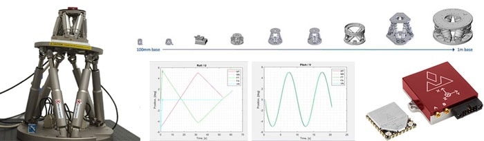
Stabilization – H-811 miniature hexapod with gyroscope mounted on H-840 hexapod. The H-840 is controlled by the C-887.52 controller’s integrated waveform generator. A Matlab program reads the output from the gyroscope on the H-811 platform and sends commands countering the H-840 motions to the H-811 controller.
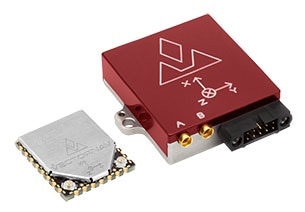
VN-300 Dual Antenna GNSS/INS (manufactured by VectorNav). Left, surface mount device. Right, ruggedized with interface. (Image: VectorNav Technologies)
Hexapod Background
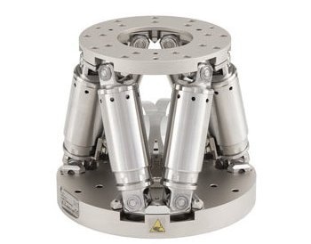
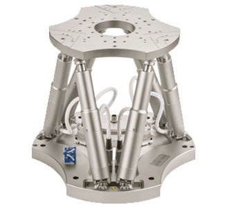
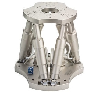
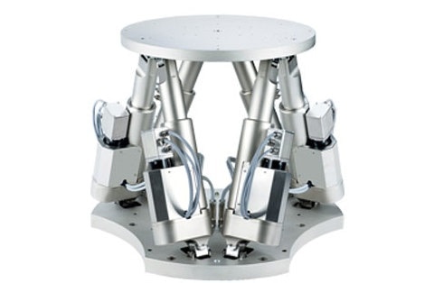
A hexapod (or Stewart Platform) is a parallel positioner with six-axis. Typically, hexapods consist of six actuators positioned in parallel between a top and bottom platform. Thus, by having six actuators in the configuration allows for the top plate to move in all six degrees of freedom (the linear axes X, Y, and Z; and the rotational axes U (roll), V (pitch), and W (yaw)). Therefore, a parallel kinematic system, such as a hexapod, also imparts a multitude of advantages over standard serial kinematic stages, including improved dynamics, lower inertia, higher stiffness, smaller package size, and less compounding errors.
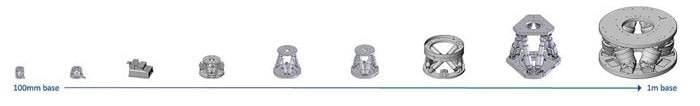
Range of standard hexapod sizes available at PI
Controlling a PI hexapod is done using a designated controller (model C-887). The C-887 can operate all of the inverse kinematic equations so that the user needs only input a target position for the top platform. Then, the controller regulates and executes the necessary displacement for each of the six struts. Also, the controller has several features which make applications straightforward to perform. For example:
- The coordinate systems are easy and open when being defined. They can be translated and/or rotated. This minimizes the effort of transforming position values if the hexapod is mounted in any non-horizontal orientation.
- The pivot point can be freely defined. This is the point about which all rotations take place. By default, the pivot point is at the default origin: centered radially on the top plate, and level with the bottom surface of the top plate. However, it is possible to move the pivot point to any XYZ point in space, which in turn enables the user to rotate about precisely where they need.
- The data recorder is configurable. This enables the user to record several aspects of the application, including actual position, target position, the amplitude of an analog signal, etc.
- Waveform generator. The user can use this to predefine a motion profile. By default, the C-887 can organize linear profiles, sinusoidal profiles, or ramps for configuration. However, the user can also define a completely custom profile point by point.
- The C-887 is effective in storing macros. This allows for semi-autonomy. The user can program the macros to run at initialization or can be later called/triggered as needed.
The following equipment was used in this test:
- 1x VN-300 gyroscope (etc.) from VectorNav
- 1x PC with Matlab
- 1x H-8xx/C-887 hexapod system from PI to simulate environmental disturbances 1x H-811/C-887 hexapod system from PI to be stabilized
- Brackets for mounting, as necessary
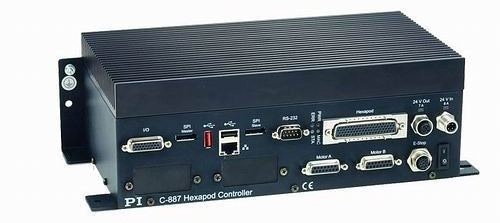
C-887.52 Hexapod controller with RS232/TCP/IP. The C-887.53 model is EtherCAT® compatible.
The gyroscopic position data was used in a control loop for an H-811 throughout each of the trials. Using PET, a bracket was 3D printed to affix the VN-300 to the top plate of an H-811. Using a second hexapod, environmental angular disturbances were produced. This ensured that the disturbances would be easily measurable, repeatable, and readily configurable. Throughout the project, multiple hexapod systems with different size, load, and velocity identifiers were used.
H-811
H-840.D2, Direct Drive Hexapod
H-850.H11, Geared Hexapod
The Matlab Program
Matlab was used in the development of the controlling program. PI provides Matlab drivers for application development, and the VN-300 could be operated as a serial device without difficulty. Therefore, a single Matlab script was written, which possesses the ability to run the project across both phases. Only a small number of specific parameters had to be assigned to configure the program for a specific trial (which hexapod systems, which phase, etc.).
Firstly, by loading the PI command libraries, the program would then validate communication with the VN-300 over USB and with both hexapod systems over TCP/IP. The hexapod systems, known as Master and Follower, would then start the process in which Master was the system which generated the disturbances, while Follower closed the loop using the feedback from the VN-300.
Subsequently, the Master hexapod system’s motion profile was then shaped into configuration. The profile was to move ±5 degrees in pitch and roll. The gyroscope was then configured, following which the motion of the Master system commenced. Once in motion, the VN-300 would be read, and the motion of the Follower system would be directed correspondingly. While these systems were in motion, each hexapod system’s data recorder was triggered, taking note of the target position and actual position of the axes. A separate record with a timestamp was kept for the VN-300 data.
Configuring the Gyroscope
Configuration of the gyroscope was done by sending a total of three commands to the VN-300, sent as ASCII strings over the open USB connection:
- $VNWRG,06,1*XX (This indicates that it is to output Yaw, Pitch, and Roll values.)
- $VNWRG,07,50*XX (This indicates the frequency at which the Yaw, Pitch, and Roll is to be output (here, 50 Hz).)
- VNRRG,05*XX (This command reads the output, and must be looped to read the values.)
The VN-300’s output frequency could be set to one of eleven different values, from 1 Hz to 200 Hz. Modeling the frequency of the output by setting it to 50 Hz or less guaranteed consistently correctly formatted results from the VN-300. Setting it to 100 Hz resulted in about 1% of all output responses being formatted incorrectly, which was probably caused by a USB issue.
One way of illustrating a correctly formatted response, as output by the VN-300, can be seen in Table 1. It has the prefix $VNYPR (VN-300, Yaw, Pitch, Roll), three numerical values for each angle measurement, and then a suffix beginning with the asterisk. However, the responses would periodically be incorrectly formatted in one of two ways when the output frequency was set at 100 Hz or above. The initial option has the response truncated and aborted at the decimal point of the Roll value. The following option would truncate the response at the decimal of the Roll value, and then append a complete response. See the examples below.
Table 1. Examples of queried responses from VN-300
| . |
. |
| Correctly Formatted Result |
$VNYPR,-043.928,-001.449,+000.058*6B |
| Incorrectly Formatted Result, Option 1 |
$VNYPR,-043.928,-001.449,+000 |
| Incorrectly Formatted Result, Option 2 |
$VNYPR,-043.928,-001.449,+000$VNYPR,-043.928,-001.449,+000.058*6B |
By writing part of the code to discard all incorrectly formatted responses, there were 30-50 responses that had to be discarded from some 5,000 responses recorded per trial.
In Sync - Follower Hexapod Mimicking the Motion of the Master Hexapod
Different hexapods were used over a series of tests. The first test implemented two H-811 systems, as the Master and the Follower placed next to one another. The VN-300 was mounted on the Master. The Follower would mimic the motion as the Master executed the motion profile.
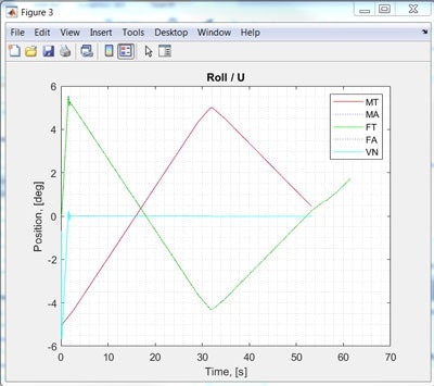
Configuration of the motion profile of the Master was set as a sinusoid for both the Pitch (V) and Roll (U) axes, with a 90˚ phase shift in the two profiles, by utilizing the waveform generator in the hexapod controller. The gyroscope data was subsequently processed, and the resulting values were fed to the Follower as a series of point-to-point move commands.
To graphically compare the recorded results at the end, the mimicking process was completed as a first attempt as this made it easier to visually judge the performance. The profile was a sine wave with a 10˚ peak-valley amplitude and a frequency of 0.1 Hz. The results are illustrated in the graphs below.
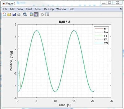
Roll results with H-811 mini hexapods as Master and Follower. MT=Master Target, MA=Master Actual, VN=VN-300 Gyroscope; FT=Follower Target, FA=Follower Actual. All lines converge. (Image: PI)
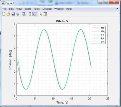
Pitch results with H-811 mini hexapods as Master and Follower. MT=Master Target, MA=Master Actual, VN=VN-300 Gyroscope; FT=Follower Target, FA=Follower Actual. All lines converge. (Image: PI)
While there are five separate lines displayed on the graphs, they quickly become one line. The success of position following is illustrated in the overlapping of the Master Target and Master Actual which indicates that there was no error in the Master hexapod. The same can be said about the Follower. The closeness of the VN-300 with the Master position plots also confirms the excellent precision of the VN-300.
Stabilizing – Follower Hexapod Countering the Motion of the Master Hexapod
During Phase 2, the H-811 system was deployed as Follower to a larger, slower hexapod, the H-850.H11. The H-811 mini hexapod was affixed to the H-850 using a customized bracket. The VN-300 gyroscope was then mounted on the H-811. The Follower would counter any motion the Master motion profile executed, this enabled a zero-value Pitch and Roll to be sustained throughout.
This H-850 used in this experiment was an older model with an angular velocity that reached a maximum 6mrad/sec and was not equipped with a waveform generator, so the motion profile was configured using point-to-point motion. This led to the position data from both the VN-300 and the Follower being queried, as the H-850 was in disturbance through the motion. The Follower was ultimately instructed to move to the difference between the two readings, as outlined in Equations 1 and 2.
| . |
. |
| Equation 1 |
Target Pitch = (Current Follower Pitch) - (Gyroscope Pitch Reading) |
| Equation 2 |
Target Roll = (Current Follower Roll) - (Gyroscope Roll Reading) |
The results from this test are displayed on the graph below. Position following error was absent for each hexapod, so the Target Position and Actual Position lines do in fact overlap. Equal in magnitude but opposed in direction, the positions of the H-850 Master and the H-811 Follower resulted in a gyroscopic reading close to 0˚.
Roll results with H-850.H11 Master and H-811 Follower (Image: PI)

Pitch results with H-850.H11 Master and H-811 Follower (Image: PI)
Due to the restrictions, the H-850 imposes on velocity led to it being replaced with the faster H-840.D2. This unit was guided by the newer C-887.52 controller with the waveform generator – the results can be seen in the video above.
Conclusions
The motivations of this project were driven by the interest to determine if it was feasible to gyroscopically stabilize a hexapod top plate if the base plate was exposed to environmental disturbances. This indeed was established to be a real possibility, simply by consistently reading the gyroscopic position data at regularity and sending a series of point-to-point motion commands to the hexapod. The setup and programming could not be fully optimized, given the time restrictions of the project, but there were multiple conclusions that could be drawn.
Due to a possible formatting issue, the rate of the query of the VN-300 had to be limited, this may have been due to a USB issue but further investigation was not possible. A higher data rate would result in improved stabilization and smoother motion.
Carried over a TCP/IP connection the tests were run with standard hexapod controllers. PI provides the C-887.53, which allows for communication over EtherCAT protocol. This hexapod controller offers better capacity for interpolation, and the EtherCAT® standard has enhanced real-time capabilities which can improve the motion between point-to-point motion commands coming from the EtherCAT® master.
High Load / High Speed Hexapods
A larger hexapod for applications that require higher speeds, greater loads, and longer travel ranges is also available. The H-900KSCO Hexapod can handle loads up to 60 kg while giving motion ranges to 200 mm (XYZ) and 66° (pitch, yaw and roll). It also offers velocity to 80 mm/sec and 30°/sec, respectively.
The voice-coil driven, flexure-guided H-860 hexapod is available for high-frequency (low load) operation. This unit utilizes fixed carbon-fiber struts and voice-coil linear motors with linear encoders merged to on all 6 legs for fully realized optimal performance.
Designed for motion simulation / stabilization of profiles compatible to ISO 20672, ISO 8728, and ISO 16328, the H-900KSCO finds use in industrial production, precision machining, the automotive industry, stabilization of motion on moving vehicles and vessels. Learn more
6-DOF Motion Platform: High Speed & Dynamics; Shaker Hexapod Motion Simulator, www.pi.ws
The video shows the H-860 high-speed hexapod. It is based on non-contact linear motors with flexure guides (in the base of the hexapod) and frictionless and backlash-free flexure joints (top and bottom of each strut) along with carbon fiber parts to further reduce the moving mass.

This information has been sourced, reviewed and adapted from materials provided by PI (Physik Instrumente) LP.
For more information on this source, please visit PI (Physik Instrumente) LP.