A biped robot is a multi-coupling, highly non-linear mobile robot. The robot’s high flexibility enables it to operate in a wide range of unstructured scenarios, allowing it to replace humans in various complex and variable tasks.
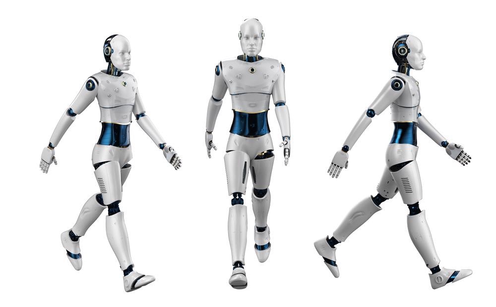
Image Credit: Phonlamai Photo/Shutterstock.com
A biped robot should be able to move quickly and steadily in dynamic motion while also being highly adaptable to its surroundings. As a result, designing a leg structure with high dynamic stability has become a challenge in biped robot design.
Researchers have developed several foot-based robots. These robots can move more efficiently without driving or with only a small amount of driving, but their movements are restricted to specific gaits and environments.
Dynamic biped robots that can walk, run, and jump simultaneously are extremely rare in the real world right now. Most biped robots are multifunctional, static, or dynamic, and have a limited gait. The main reason is that the leg structure lacks natural compliance, making it impossible to achieve organic physical interaction between the biological legs and the environment.
A kinematics model and a primary prototype of a leg structure based on a spring-mass model are developed in this study. The researchers focused on this compliant actuated bipedal robot’s leg topology for kinematics analysis, prototype building, and preliminary performance testing to facilitate further research and experimental platform of a compliant actuated bipedal robot.
Methodology
The leg structure analyzed in this study is a hybrid structure based on the spring-mass model. Figure 1 reveals the XOZ plane of the robot.
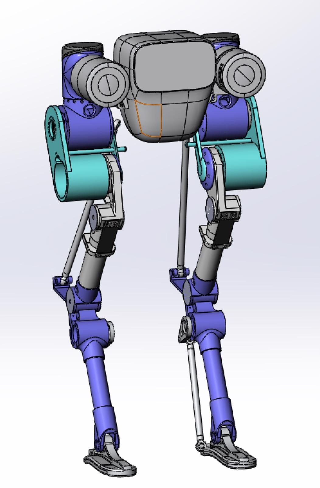
Figure 1. Simulation model of biped robot. Image Credit: Che, et al., 2022
Figure 2 depicts a biped robot’s side view and mechanism diagram. Dynamic analysis is required because spring elastic deformation occurs when it is subjected to a relatively large impact in dynamic motion.
The spring is assumed to be a rigid body in kinematics analysis. The difficulty of solving kinematics is greatly reduced as a result of this. The actual structure sketch for kinematics analysis is shown in the diagram as a dashed line.
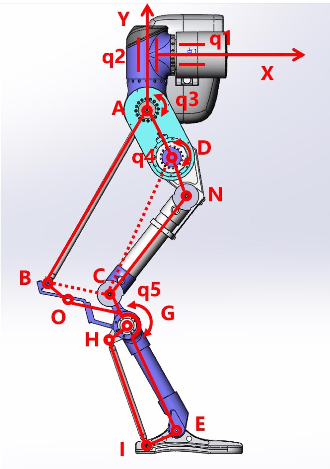
Figure 2. Side view and mechanism diagram of biped robot simulation model. Image Credit: Che, et al., 2022
The positive kinematics are solved using the structure. According to the spinor theory, the pose matrix of the corresponding joint can be obtained only by knowing the position and rotation direction of each active joint. Finally, multiplying them one by one can solve the active joint’s end position of joint rotation.
The goal of inverse kinematics is to evaluate the rotation of the active joint that corresponds to the end displacement when the robot moves. To lower the complexity of calculating the inverse solution, the end is converted into the corresponding coordinate in the leg plane coordinate system. Figure 3 reveals the foot end geometry.
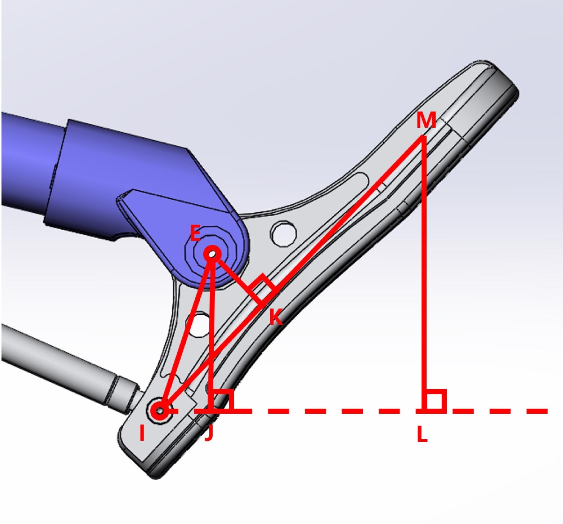
Figure 3. Foot end geometry. Image Credit: Che, et al., 2022
One-legged simulation is used to validate kinematics. The robot’s walking gait is simulated to demonstrate the correctness of the inverse kinematics. Figure 4 shows a simulation of the robot walking in a stable manner.
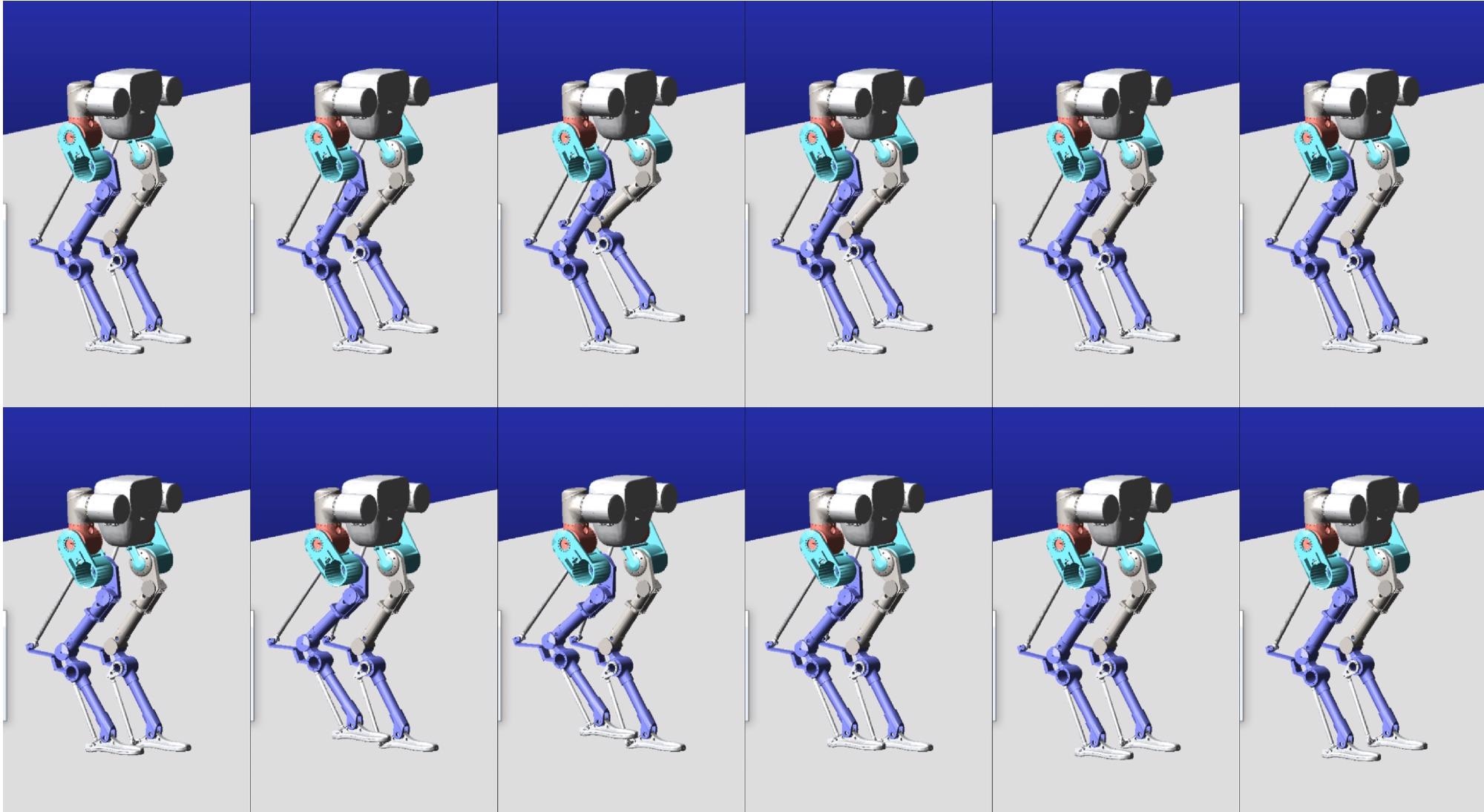
Figure 4. Step simulation. In the simulation, the robot steps at a speed of 4 mm/ms. The above figure shows two steps in intercepting the robot’s motion. Image Credit: Che, et al., 2022
The first-generation prototype, as shown in Figure 5, was used in this study. The first-generation prototype is built independently, based on the Cassie leg structure and the size and weight of the driving module.
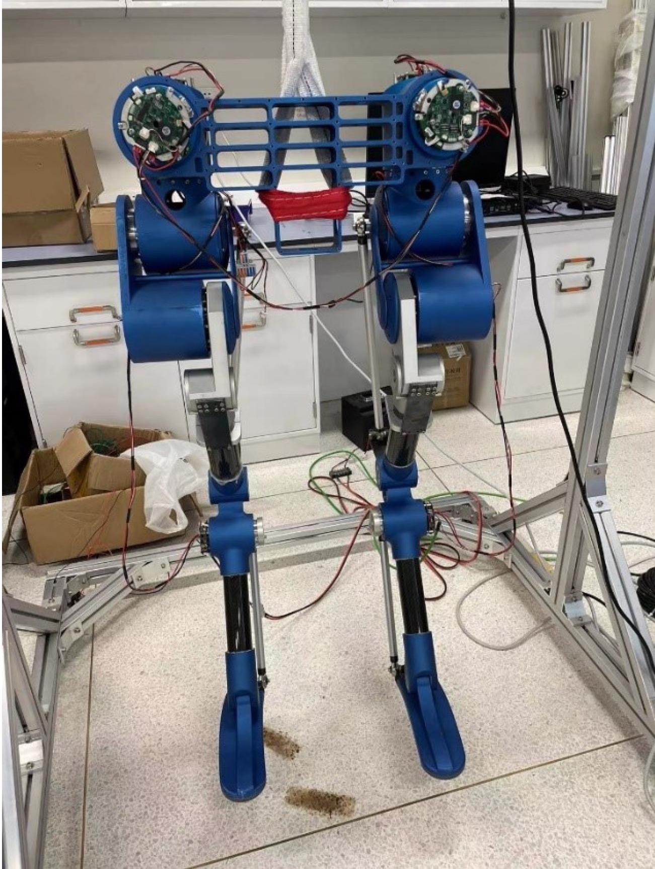
Figure 5. Experimental Prototype. Image Credit: Che, et al., 2022
Weight has a significant impact on the performance of foot-type robots, particularly biped robots. As a result, the mechanical structure needs to be as light as possible. Figure 6 depicts the experimental prototype from the side. The motor housing and all connectors are made of aluminum alloy.
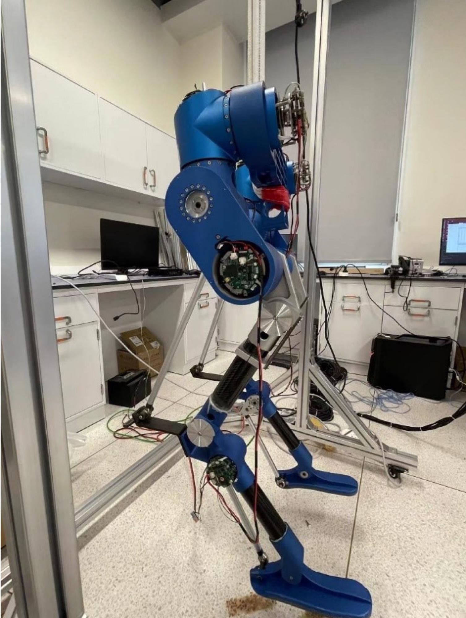
Figure 6. Side view of experimental prototype. Image Credit: Che, et al., 2022
Carbon fibers reduce the weight at the end of the leg and the end rotator’s inertia. Figure 7 shows a four-bar mechanism for the knee joint. The four-bar mechanism creates a distortion that lifts the lower leg, allowing the knee to bend by turning the active joint.
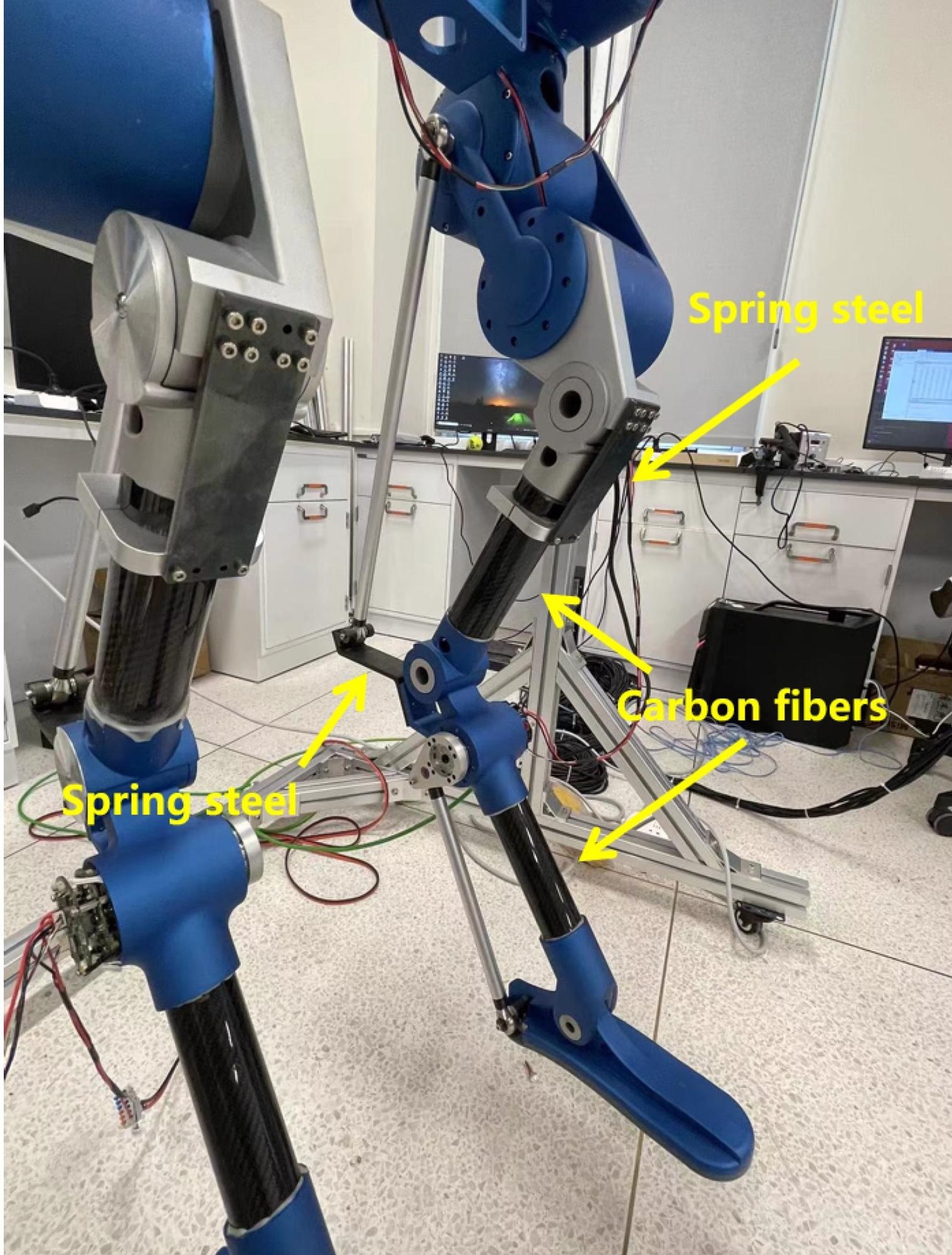
Figure 7. Inside view of experimental prototype. Image Credit: Che, et al., 2022
For biped robots, the development of compact and lightweight transmission systems is critical. Hence, drivers use an integrated module to reduce joint space and weight. Figure 8 depicts the motor module’s composition.
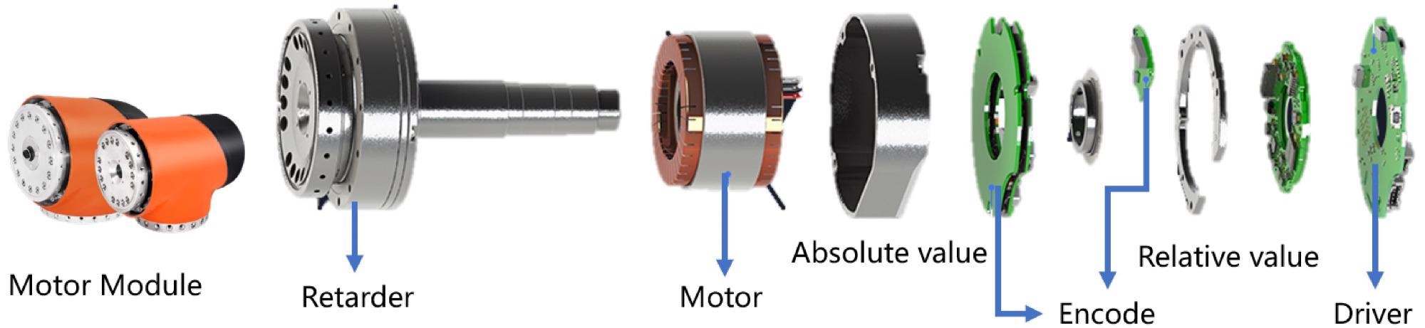
Figure 8. Composition of motor module. Image Credit: Che, et al., 2022
A self-designed controller is majorly responsible for robot control. The controller is a real-time system that runs on Linux. EtherCAT, an industrial Ethernet bus technology, and Xenomai, a powerful real-time extension of the Linux kernel, are primarily responsible for its real-time performance. Millisecond-level motion control is achieved by combining the two, allowing the robot to perform more efficiently.
Results and Discussion
The challenge in developing a biped robot prototype is balancing the organic relationship between motor performance and weight. A series of experiments were carried out that were primarily divided into suspension and ground steps.
The first part of the study, experiment A, involves walking through the air, while the second, experiment B, is a walking experiment on flat ground.
The robot prototype is hoisted by a gantry with a lifting function, as shown in Figure 9. As the prototype is very heavy and can easily damage the robot’s structure and motor if it falls, the gantry’s primary function is to protect the robot by hanging it when it is about to fall.
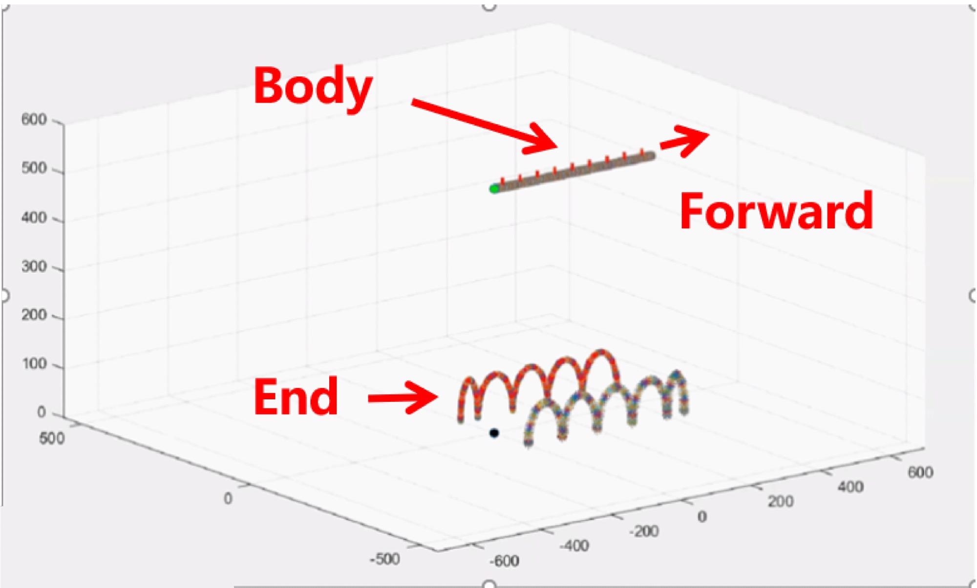
Figure 9. Trajectory planning of body and end. Image Credit: Che, et al., 2022
The main goal of this experiment is to see if the motor can meet the biped robot’s dynamic motion performance requirements. Determining whether the robot is stable or not can be comprehended by looking at how it moves in the air and on the ground.
Experiment A’s main goal is to analyze if the robot can follow the instructions and comprehend the maximum speed of the robot’s final movement. Figures 10 and 11 show the screenshot and data from the experiment.
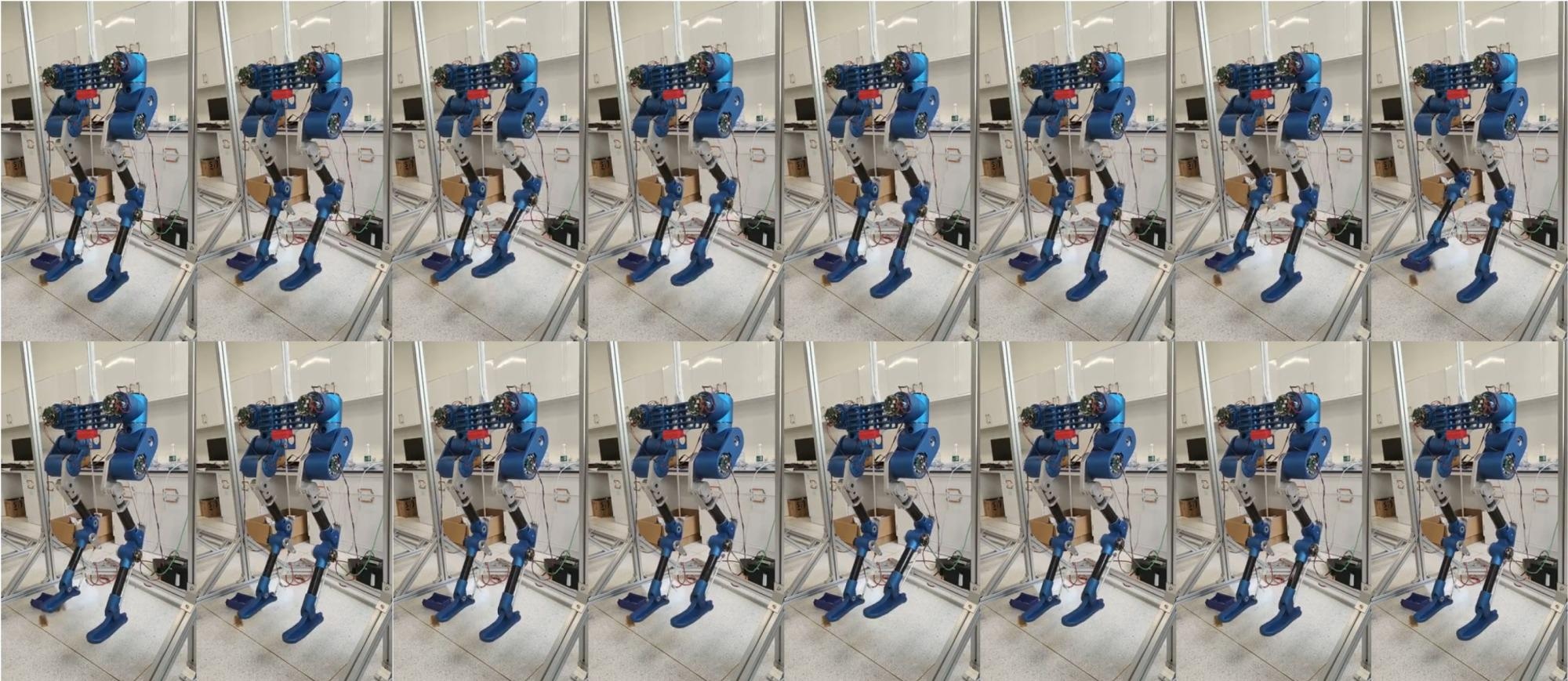
Figure 10. The prototype walks step in the air. Image Credit: Che, et al., 2022
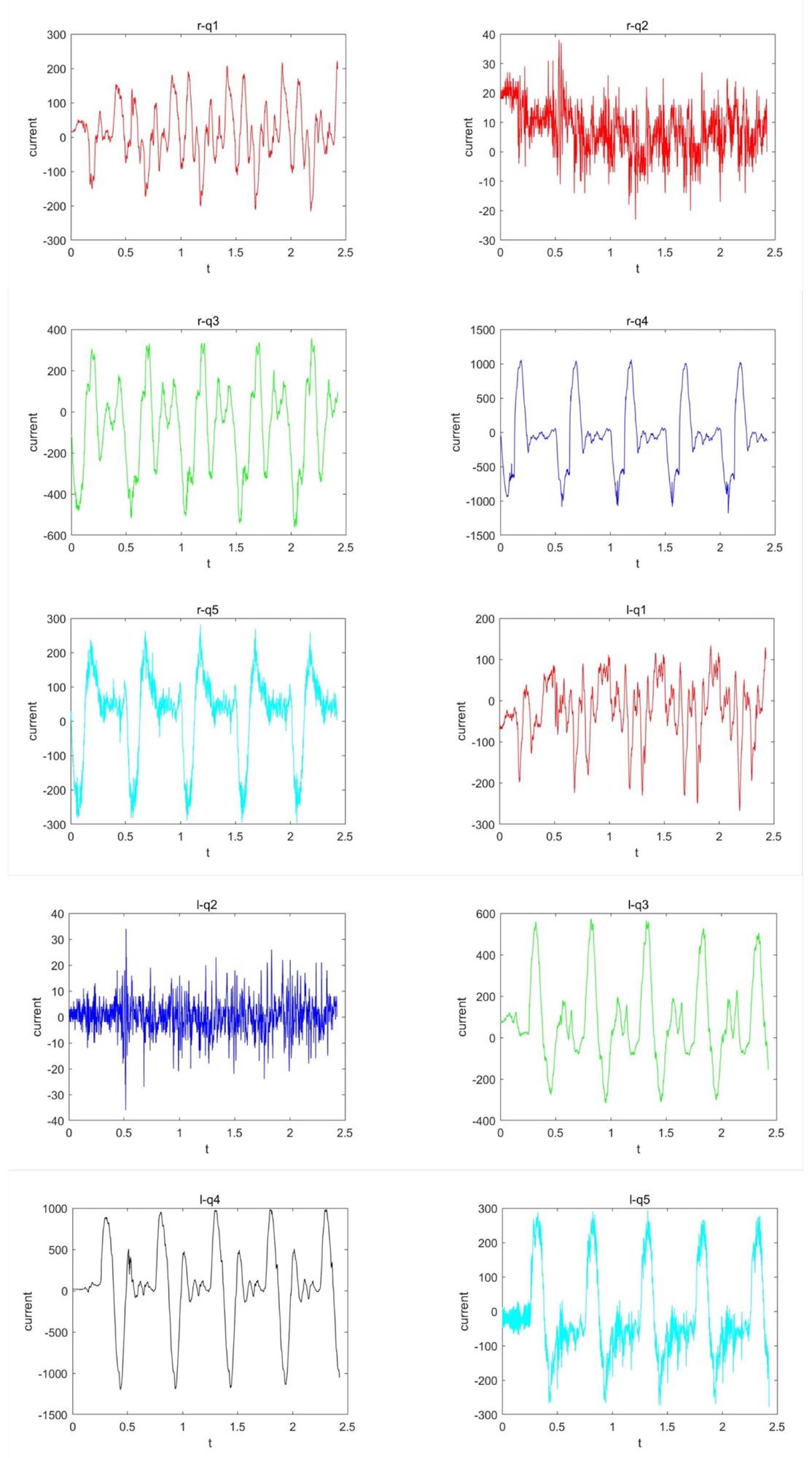
Figure 11. Experiment data. When the trapezoidal trajectory speed is 8 mm/MS, this is the motor current data collected by the robot motion. It can be seen from the figure that when the robot moves at the current speed, it approaches the performance limit of the motor, and even has a short-term current overload. Image Credit: Che, et al., 2022
Experiment B’s main goal is to analyze if the robot’s motor performance can keep up with its demands. The robot’s actual motion diagram and the collected data diagram are shown in Figures 12 and 13.

Figure 12. The prototype walks step on flat ground. Image Credit: Che, et al., 2022
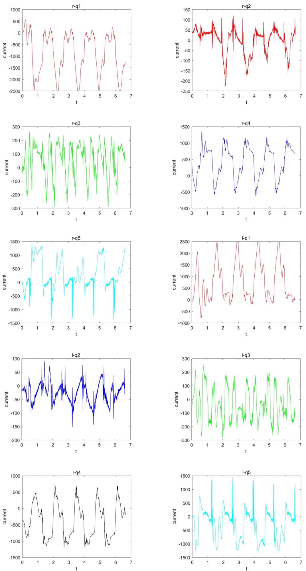
Figure 13. Experiment data. When the robot steps at the speed of 3 mm/ms on the ground, the current data collected by the driver. Some motors exceed the rated current during movement, and even greatly exceed the rated current for a long time. Among them, the motor q1 once exceeds more than twice the rated current during movement. Image Credit: Che, et al., 2022
Conclusion
The forward and inverse kinematics of a hybrid mechanism based on a spring-mass model are modeled and solved in this paper. A biped robot prototype is then built based on this leg structure. Structural parts and motors are assembled on the prototype body.
The prototype will need to be further optimized in the future. Addressing the body's heavy weight and insufficient motor performance are required to meet the motion requirements. Finally, biped robot walking necessitates a high level of balance and stability. The simulation environment’s feedback data differs from that of the prototype; hence, there is still a long way to go before the robot is fully functional.
Journal Reference:
Che, J., Pan, Y., Yan, W., Yu, J. (2022) Leg Configuration Analysis and Prototype Design of Biped Robot Based on Spring Mass Model. Actuators, 11(3), p. 75. Available Online: https://www.mdpi.com/2076-0825/11/3/75/htm.
References and Further Reading
- Dynamics, B (2021) Atlas [EB/OL]. Available at: https://www.bostondynamics.com/atlas.
- Dynamics, B (2021) Do You Like Me? [EB/OL]. Available at: https://www.youtube.com/watch?v=fn3KWM1kuAw&ab_channel=BostonDynamics.
- Honda (2021) ASIMO [EB/OL]. Available at: https://global.honda/innovation/robotics/ASIMO.html.
- Shigemi, S., et al. (2019) ASIMO and humanoid robot research at Honda. In: Humanoid Robotics: A Reference; Springer Nature B.V.: Dordrecht, The Netherlands, 2019; pp. 55–90. Available at: http://www1.cs.columbia.edu/~allen/S19/ASIMO.pdf.
- Lohmeier, S., et al. (2009) Humanoid robot LOLA. In:2009 IEEE International Conference on Robotics and Automation, Kobe, Japan, 12–17 May 2009; IEEE: Piscataway, NJ, USA, 2009; pp. 775–780.doi.org/10.1109/ROBOT.2009.5152578.
- ubtRobot (2021) Walker [EB/OL]. Available at: https://www.ubtrobot.com/web2/template/index.shtml
- Akachi, K., et al. (2005) Development of humanoid robot HRP-3P. In:5th IEEE-RAS International Conference on Humanoid Robots, Tsukuba, Japan, 5 December; IEEE: Piscataway, NJ, USA, pp. 50–55.doi.org/10.1109/ICHR.2005.1573544.
- Kaneko, K., et al. (2019) Humanoid robot HRP-5P: An electrically actuated humanoid robot with high-power and wide-range joints. IEEE Robotics and Automation Letters, 4(2), pp. 1431–1438.doi.org/10.1109/LRA.2019.2896465.
- Englsberger, J., et al. (2014) Overview of the torque-controlled humanoid robot TORO. In:2014 IEEE-RAS International Conference on Humanoid Robots, Madrid, Spain, 18–20 November ; IEEE: Piscataway, NJ, USA, pp. 916–923. doi.org/10.1109/HUMANOIDS.2014.7041473.
- Mesesan, G., et al. (2019) Dynamic walking on compliant and uneven terrain using DCM and passivity-based whole-body control. In:2019 IEEE-RAS 19th International Conference on Humanoid Robots (Humanoids), Toronto, ON, Canada, 15–17 October; IEEE: Piscataway, NJ, USA, pp. 25–32. doi.org/10.1109/Humanoids43949.2019.9035053.
- Hubicki, C., et al. (2016) ATRIAS: Design and validation of a tether-free 3d-capable spring-mass bipedal robot. The International Journal of Robotics Research, 35(12), pp. 1497–1521. doi.org/10.1177%2F0278364916648388.
- Hobbelen, D., et al. (2008) System overview of bipedal robots flame and tulip: Tailor-made for limit cycle walking. In:2008 IEEE/RSJ International Conference on Intelligent Robots and Systems, Nice, France, 22–26 September , IEEE: Piscataway, NJ, USA, pp. 2486–2491. doi.org/10.1109/IROS.2008.4650728.
- Collins, S., et al. (2005) Efficient bipedal robots based on passive-dynamic walkers. Science, 307(5712), pp. 1082–1085. doi.org/10.1126/science.1107799.
- Russo, M., et al. (2018) Development of LARMbot 2, A Novel Humanoid Robot with Parallel Architectures. In: IFToMM Symposium on Mechanism Design for Robotics; Springer: Berlin/Heidelberg, Germany, pp. 17–24. doi.org/10.1007/978-3-030-00365-4_3.
- Bhounsule, P. A., et al. (2014) Low-bandwidth reflex-based control for lower power walking: 65 km on a single battery charge. The International Journal of Robotics Research, 33(10), pp. 1305–1321. doi.org/10.1177%2F0278364914527485.
- Renjewski, D., et al. (2014) Exciting passive dynamics in a versatile bipedal robot. IEEE Transactions on Robotics; submitted.
- Blickhan, R., et al. (2007) Intelligence by mechanics. Philosophical Transactions of the Royal Society A: Mathematical, Physical and Engineering Sciences, 365(1850), pp. 199–220. doi.org/10.1098/rsta.2006.1911.
- Robotics, A (2021) Agility Robotics [EB/OL]. Available at: https://www.agilityrobotics.com/robots#digit
- Abate, A M (2018) Mechanical Design for Robot Locomotion. Ph.D. Thesis, Oregon State University, Corvallis, OR, USA. Available at: https://ir.library.oregonstate.edu/concern/graduate_thesis_or_dissertations/nk322k39g.
- Apgar, T., et al. (2018) Fast Online Trajectory Optimization for the Bipedal Robot Cassie. Robotics: Science and Systems, 101, p. 14. Available at: http://www.roboticsproceedings.org/rss14/p54.pdf.
- Gong, Y., et al. (2019) Feedback control of a cassie bipedal robot: Walking, standing, and riding a segway. In:2019 American Control Conference (ACC), Philadelphia, PA, USA, 10–12 July; IEEE: Piscataway, NJ, USA, pp. 4559–4566. doi.org/10.23919/ACC.2019.8814833.
- Westervelt, E.R., et al. (2018) In: Feedback Control of Dynamic Bipedal Robot Locomotion; CRC Press: Boca Raton, FL, USA. doi.org/10.1201/9781420053739.
- Che, J., et al. (2021) Kinematics Analysis of Leg Configuration of An Ostrich Bionic Biped Robot. In:2021 International Conference on Robotics and Control Engineering, Tokyo, Japan, 22–25 April 2021; pp. 19–22. doi.org/10.1145/3462648.3462652.