Underwater robots can explore oceans and aquatic environments using a variety of propulsion systems, including main propellers and biomimetic systems. Bio-robots have shown promise in terms of being integrated (and even assimilated) into aquatic ecosystems. They exploit fluid-mechanical principles with their super-streamlined bodies, achieving incredible acceleration, propulsion efficiencies, and maneuverability.
Engineers are increasingly utilizing the excellent swimming abilities of fish to create biomimetic underwater robots that exceed traditional underwater vehicles. The undulatory motions of fish can be divided into two types of propulsion modes: body/caudal fin propulsion (BCF mode) and central fin/counter fin propulsion (MPF mode).
Conventionally, driving elements such as hydraulics and motors have been used in the design of BCF bionic fish. It can be seen that most recent fish robots with a single joint use a variety of methods to swing their caudal fins, including indirect or direct driving, motors, and linkage mechanisms.
When a robot fish is driven by a motor (indirectly or directly), only the caudal fin swings; the fish body and caudal peduncle remain rigid and stationary, inconsistent with how fish actually swim.
A paper published in the journal Machines proposes a design method for a single-joint bionic robotic fish on the basis of a conjugate cam mechanism, which can achieve a specific tail swing of the robotic fish with a single motor’s uniform rotation and greatly reduces the control system’s accuracy requirements. To improve the accuracy of motion of the robotic fish, the profile of the cam can be changed to imitate various swinging postures.
Methodology
A cam mechanism was chosen over a four-bar linkage as the bionic robotic fish’s transmission mechanism to achieve a customized swing motion of the caudal fin. As a caudal fin’s swing motion is bidirectional, a coaxial double-cam mechanism was proposed. Figure 1 depicts a schematic of the mechanism.
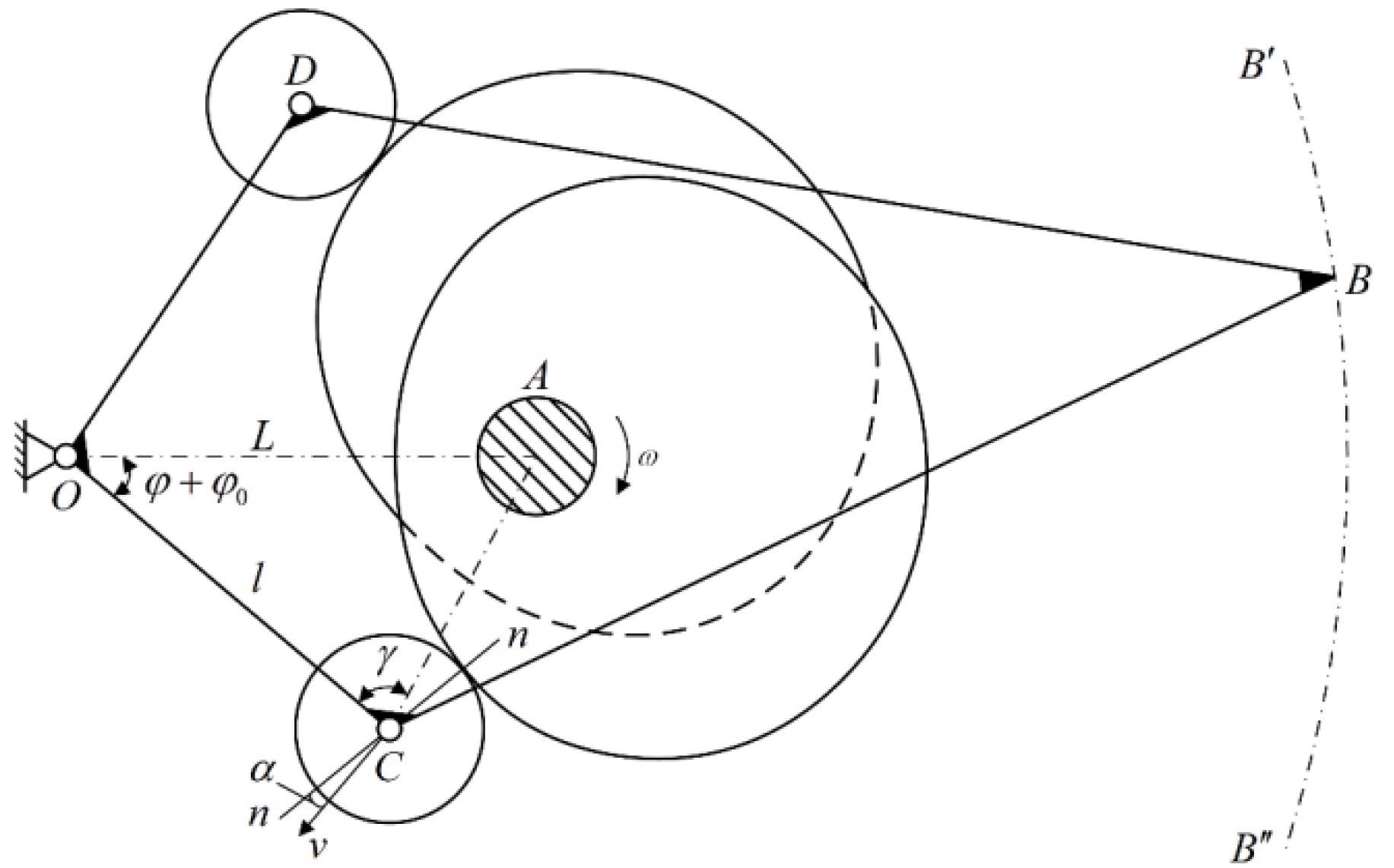
Figure 1. Schematic diagram of the proposed double-cam mechanism. Image Credit: Song, et al., 2022
The proposed double-cam mechanism’s follower, frame O-C-B-D, is shown in Figure 1 and reveals an intermediate status, which is a one-half-cycle process.
The follower can swing back and forth due to the continuous rotation of the double-cam in this design. The fish robot’s back has a swing motion that corresponds to the follower. Table 1 lists the structural parameters of the fabricated prototype.
Table 1. The dimension parameters of the double-cam mechanism. Source: Song, et al., 2022
| Parameter |
Value |
| Center distance L/mm |
20 |
| Length of pendulum rod l/mm |
18 |
| Radius of base circle of cam Rb/mm |
10 |
| Roller radius Rr/mm |
4 |
Two types of motion were investigated to see how the BCF model’s undulatory motion affected the swimming performance of bionic robotic fish. The theoretical profiles of the cams that achieve the two wave motions are shown in Figure 2. The cams can rotate around the axis of rotation, and the robot fish use the two cams to simulate the movement of a real fish as well as cycloid movement.
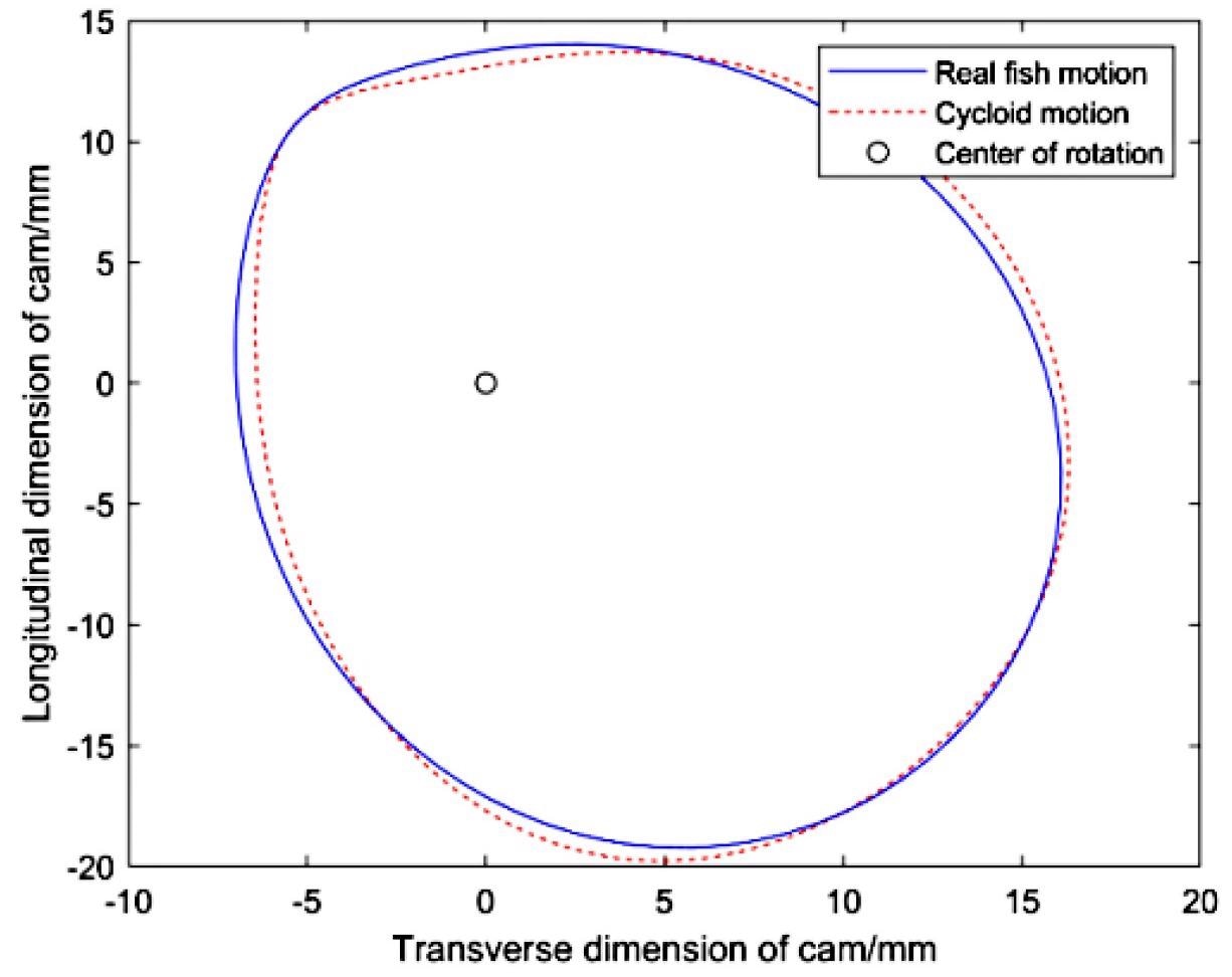
Figure 2. The two cam profiles for achieving real fish motion and cycloid motion. Image Credit: Song, et al., 2022
The torque provided by the motor on the single joint provided the power for driving the bionic robot fish. The torque was transferred to the force that caused the caudal fin to oscillate from one side to the other by the double-cam mechanism.
The water propelled by the caudal fin drove the mobility of the fish robot. Once the caudal fin propelled water, dynamic analysis was performed, as shown in Figure 3. Under the two motion patterns, a kinetic analysis of the maximum input torque needed was performed.
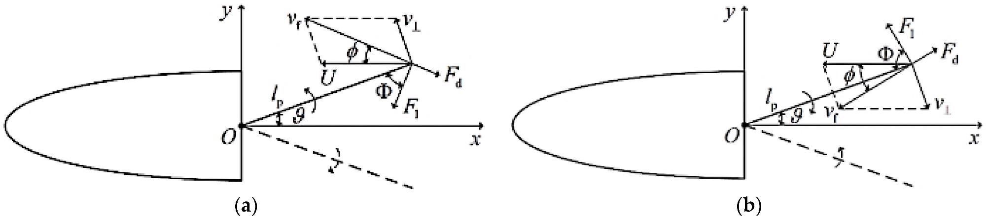
Figure 3. Force analysis of undulatory motion of fish robot: (a) caudal fin swings to both sides from the middle position (x-axis); (b) caudal fin swing back to the middle position (x-axis) from both sides. Image Credit: Song, et al., 2022
The motor’s driving torque was calculated, as seen in Figure 4. The maximum torque output under the cycloid motion law was greater than that under the real fish law, as shown in Figure 4.
When the two motions are compared, it is clear that the robot fish uses less energy to reach the same speed as the real fish. The motion laws have an impact on the robot fish’s swimming ability.
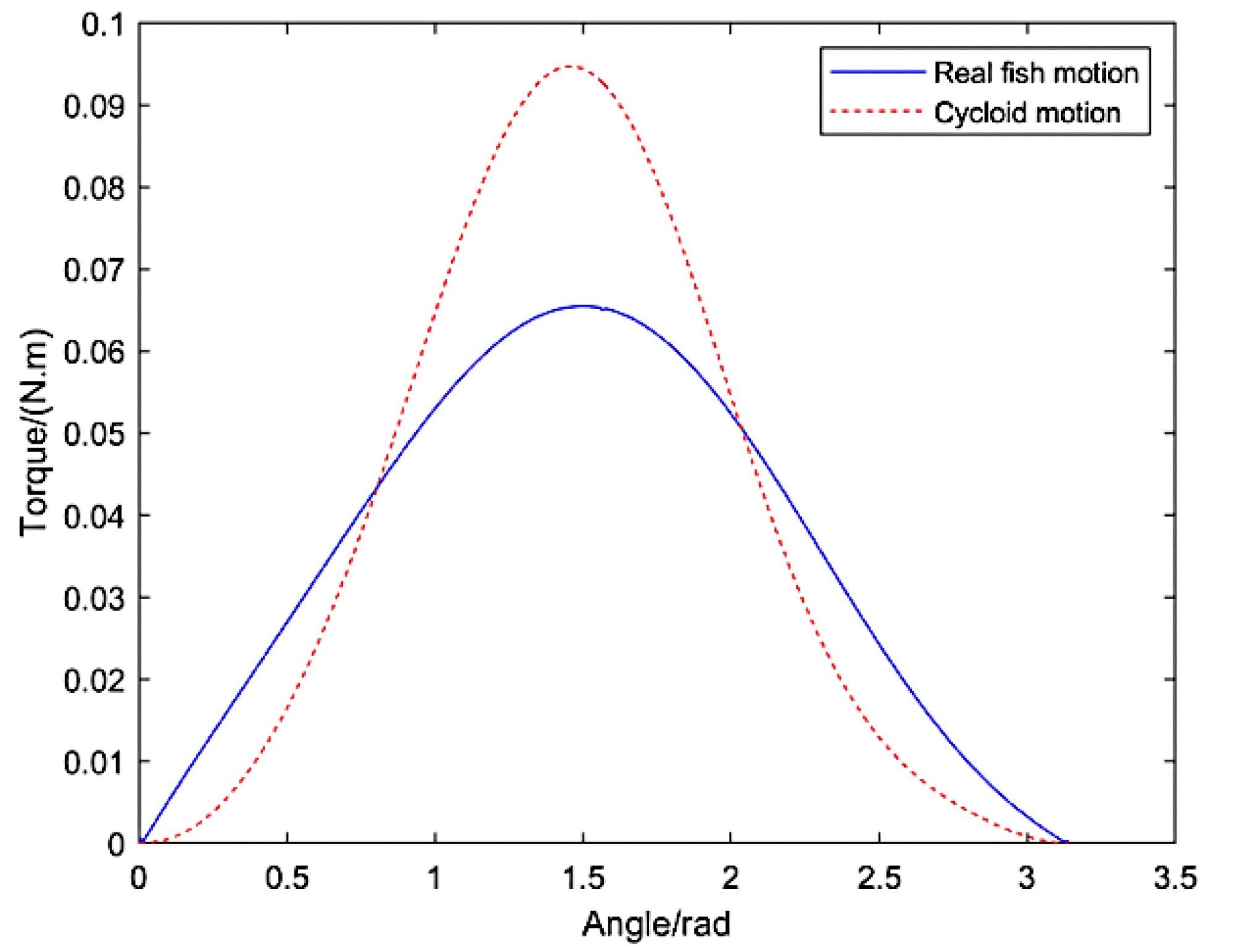
Figure 4. The driving torque for each motion. Image Credit: Song, et al., 2022
The robotic fish’s structure was based on the shape of a crucian carp, as shown in Figure 5. The fish head was made of UV curable resin and was printed using 3D printing technology.
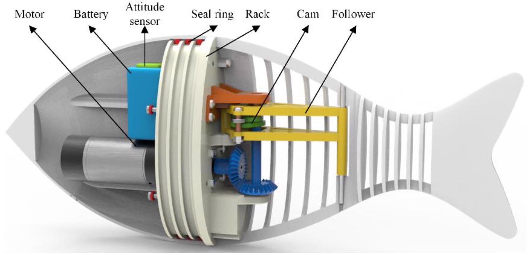
Figure 5. The structural model of the proposed robotic fish. Image Credit: Song, et al., 2022
In the anterior of the fish robot, a brushless DC motor (Table 2), battery, and control system were installed. The fishtail is made of nylon, which is a flexible material. The size of the upper and lower “spines” could be changed to alter the stiffness of the caudal peduncle.
A lithium battery provided the power supply.
Table 2. Parameters of the DCX 32L motor. Source: Song, et al., 2022
| Parameter |
Value |
| Norminal voltage U/V |
24 |
| Normial speed n/rpm |
453 |
Normial torque T/NM
Normial current I/AReduction ratio |
0.57
2.875/3:1 |
Results
Experiments on the fish robot’s swimming with two different types of double-cam mechanisms were conducted to verify the proposed fish robot’s performance. Figure 6 depicts a series of photos taken from a video of the robotic fish swimming in a single cycle during stable swimming.
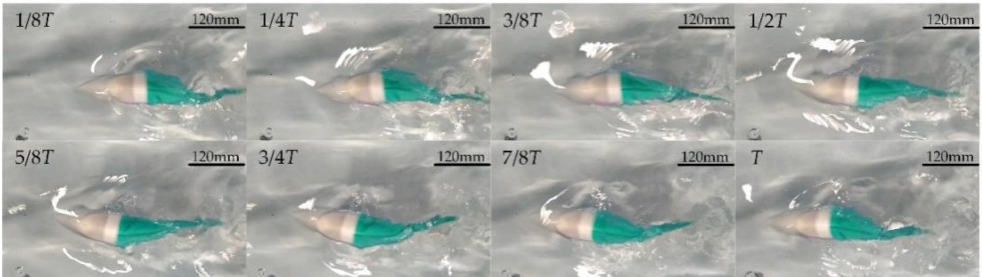
Figure 6. Sequence photos of robotic fish swimming. Image Credit: Song, et al., 2022
Swimming speed variation was measured with caudal fin swing frequency when the robot fish attained stable swimming in two motions was measured in the experiments. The velocity curves for two types of caudal peduncle stiffness are shown in Figure 7.
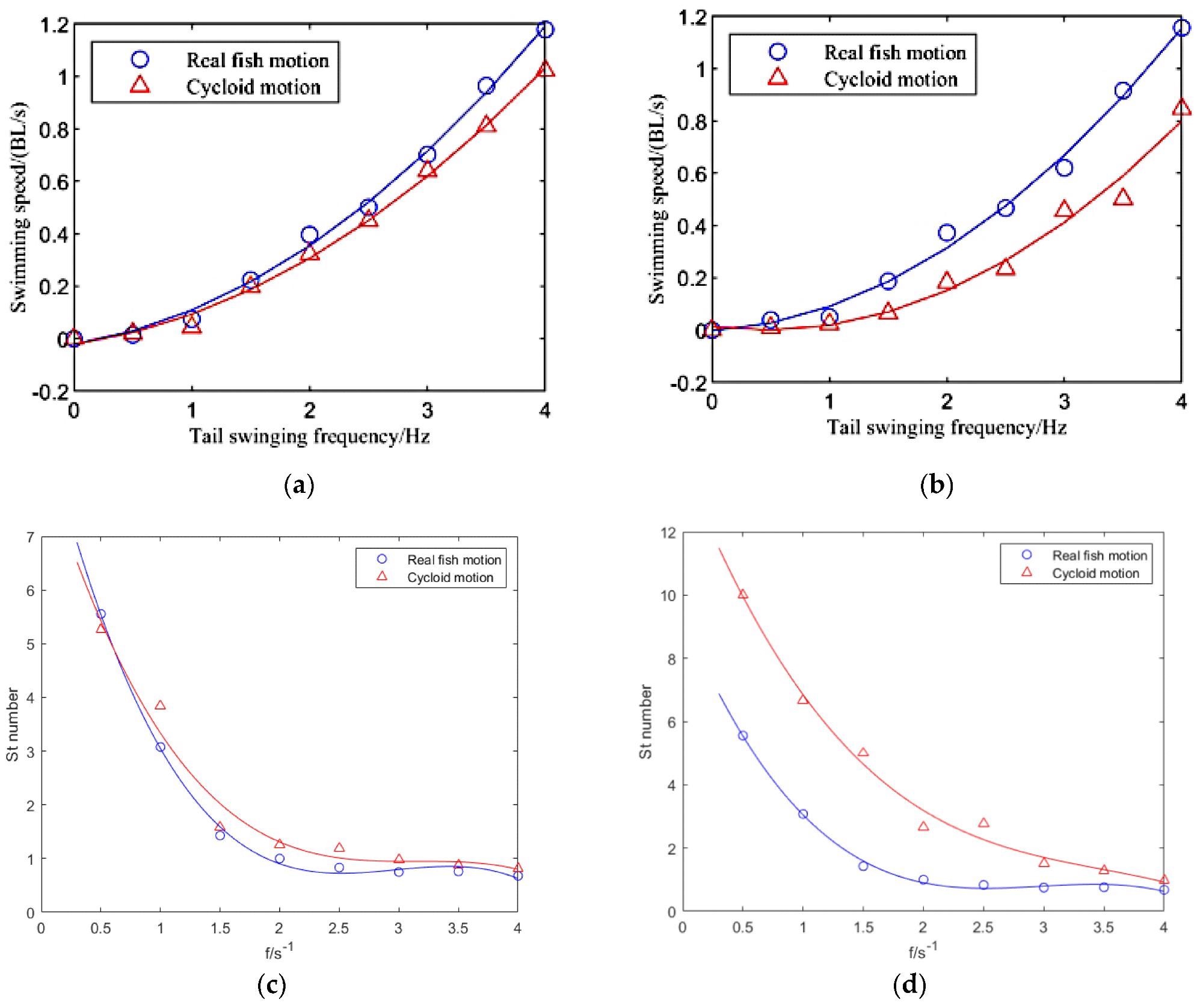
Figure 7. Velocity and St number of the fish robot when it swims in two motions at different frequencies. (a) Velocity of 1.5 mm-thick caudal peduncle. (b) Velocity of 2 mm-thick caudal peduncle. (c) St number of 1.5 mm-thick caudal peduncle. (d) St number of 2 mm-thick caudal peduncle. Image Credit: Song, et al., 2022
Figure 7 depicts differences in the swimming speeds of the robotic fish when subjected to various motions; the experimental results show that different caudal fin motions lead to different swimming performances.
The authors measured the robot fish’s acceleration before reaching stable swimming under two types of motion laws and distinct tail swing frequencies in the experiment, as shown in Figure 8.
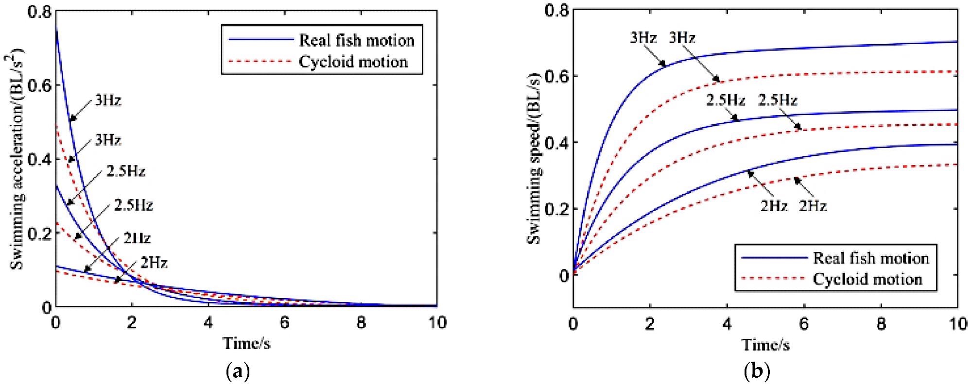
Figure 8. Acceleration ability of robotic fish under different undulatory motions: (a) the acceleration during swimming; (b) the velocity during swimming. Image Credit: Song, et al., 2022
The caudal peduncle stiffness affected the swimming speed, according to the researchers. Figure 9 depicts the swimming speeds of the two types of motions with different stiffness values for the caudal peduncle.
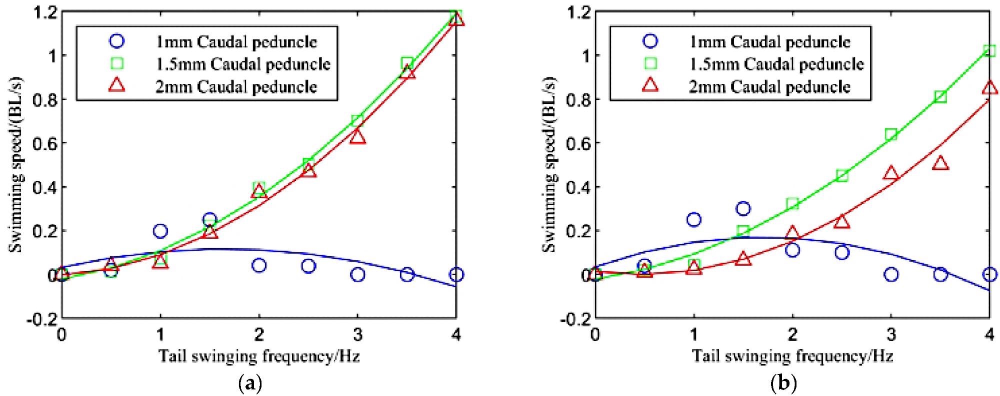
Figure 9. Swimming speeds of three types of motions with different stiffness of the caudal peduncle: (a) real fish motion; (b) cycloid motion. Image Credit: Song, et al., 2022
Figure 9 shows that the robot fish with the lowest caudal peduncle stiffness has the greatest swimming performance and the fastest swimming speed when the frequency is low.
Conclusion
A novel double-cam fish robot based on one active joint was developed in this study, with its caudal fin driven by a currently proposed double-cam mechanism. The results of a dynamic analysis of the mechanism revealed that various tail swinging motions affected the robot fish’s swimming effect.
The experiments show that when the robot fish reproduces the real fish motion of the caudal fin, it performs better. Furthermore, the stiffness of the caudal peduncle impacts swimming performance. A robot fish with a low caudal peduncle stiffness has a higher speed when the tail swinging frequency is low, and a robot fish with a high caudal peduncle stiffness has a higher speed when the tail swinging frequency is increased.
Fish robots will be assessed in natural waters, like the sea, in the future. In addition, additional sensors will be integrated into this fish robot to allow it to explore the real-world sea environment.
Journal Reference:
Song, Z., Fu., Romano, D., Dario, P., Kang, R. (2022) A Novel Fish-Inspired Robot with a Double-Cam Mechanism. Machines, 10(3), p. 190. https://www.mdpi.com/2075-1702/10/3/190/htm.
References and Further Reading
- Costanza, R (1999) The ecological, economic, and social importance of the oceans. Ecological Economics, 31(2), pp. 199–213. doi.org/10.1016/S0921-8009(99)00079-8.
- Low, K H (2006) Locomotion and Depth Control of Robotic Fish with Modular Undulating Fins. International Journal of Automation and Computing, 3, pp. 348–357. doi.org/10.1007/s11633-006-0348-6.
- Triantafyllou, M S & Triantafyllou, G S (1995) An efficient swimming machine. Scientific American, 272(3), pp. 64–70. Available at: https://www.jstor.org/stable/24980373.
- Liao, J C (2007) A review of fish swimming mechanics and behaviour in altered flows. Philosophical Transactions of the Royal Society B, 362(1487), pp. 1973–1993. doi.org/10.1098/rstb.2007.2082.
- Breder, C M (1926) The locomotion of fishes. Zoologica: Scientific Contributions of the New York Zoological Society, 4(5), pp. 159–297. doi.org/10.5962/p.203769.
- Wang, A., et al. (2016) Development and analysis of body and/or caudal fin biomimetic robot fish. Journal Mechanical Engineering, 52(17), pp. 137–146. doi.org/10.3901/JME.2016.17.137.
- Sfakiotakis, M., et al. (1999) Review of fish swimming modes for aquatic locomotion. IEEE Journal of Oceanic Engineering, 24(2), pp. 237–252. doi.org/10.1109/48.757275.
- Liang, J., et al. (2005) Trial voyage of SPC-II fish robot. Journal of Beijing University of Aeronautics and Astronautics, 31, pp. 709–713.
- Liang, J., et al. (2010) Propulsive and maneuvering performance of two joints biorobotic autonomous undersea vehicle SPC-III. In: 2009 IEEE International Conference on Robotics and Biomimetics (ROBIO), Guilin, China, 19–23 December 2010. doi.org/10.1109/ROBIO.2009.5420664.
- Wu, W (2010) Experimental Research on the Propulsion Performance of Carangiform Robotic Fish. Master’s Thesis, Department Mechanical School, University of Science and Technology of China, Hefei, China.
- Lachat, D., et al. (2006) BoxyBot: A swimming and crawling fish robot controlled by a central pattern generator. In: The First IEEE/RAS-EMBS International Conference on Biomedical Robotics and Biomechatronics, 2006. BioRob, Pisa, Italy, 20–22 February 2006. doi.org/10.1109/BIOROB.2006.1639162.
- Wang, F., et al. (2012) Cruising performance analysis and experiments of biomimetic robotic fish. Journal of University of Science and Technology Beijing, 34(1), pp. 80–84. Available at: https://www.researchgate.net/publication/286990100_Cruising_performance_analysis_and_experiments_of_biomimetic_robotic_fish
- Wang, J & Tan, X (2013) A dynamic model for tail-actuated robotic fish with drag coefficient adaptation. Mechatronics, 23(6), pp. 659–668. doi.org/10.1016/j.mechatronics.2013.07.005.
- Cheng, Y & Shuai, C (2018) Kinematic Analysis and Simulation of the One-Link and Fin-Driven Robot Fish. The Journal of Ocean Technology, 37, pp. 7–14.
- Ge, L & Li, Z (2016) The speed optimization of robotic fish propelled by caudal fin. Journal of Lanzhou Jiaotong University, 35, pp. 18–23.
- Zhu, J., et al. (2019) Tuna robotics: A high-frequency experimental platform exploring the performance space of swimming fishes. Science Robotics, 4(34), p. eaax4615. doi.org/10.1126/scirobotics.aax4615.
- Costa, D., et al. (2020) Design of a Carangiform Swimming Robot through a Multiphysics Simulation Environment. Biomimetics, 5(4), p. 46. doi.org/10.3390/biomimetics5040046.
- Zhong, Y & Du, R (2016) Design and Implementation of a Novel Robot Fish with Active and Compliant Propulsion Mechanism. In: 2016 Robotics: Science and Systems Conference, Ann Arbor, MI, USA, 18–19 June. Available at: http://www.roboticsproceedings.org/rss12/p11.pdf
- Vu, M. T., et al. (2020) Study on dynamic behavior of unmanned surface vehicle-linked unmanned underwater vehicle system for underwater exploration. Sensors, 20(5), p. 1329. doi.org/10.3390/s20051329.
- Maertens, A. P., et al. (2015) Efficiency of fish propulsion. Bioinspiration & Biomimetics, 10, p. 046013. doi.org/10.1088/1748-3190/10/4/046013.
- Piskur, P., et al. (2021) Innovative energy-saving propulsion system for low-speed biomimetic underwater vehicles. Energies, 14(24), p. 8418. doi.org/10.3390/en14248418.