Origami-like folding is a cost-effective structural design that retains flexible and stiff characteristics. By utilizing an appropriate actuation method, origami-folded structures can be employed in various fields. For example, medical stents require easy expansion and reduction of size when trying to navigate narrow spaces.
Suitable actuation mechanisms may be pneumatic, tendon-driven, magnetic, piezoelectric, or shape memory alloys. Each method has its own set of disadvantages, such as control difficulty when traveling through narrow complex pathways, achieving sharp turns in narrow paths, and leaking.
Shape memory actuation cannot be used where quick movement of the robot is involved. However, earlier studies have identified magnetic fields as a more suitable actuation mechanism. Permanent magnets, in particular, are easily controllable and can be scaled up or down to the needed application.
This research reveals an origami-based soft robot containing various configurations of iron (paramagnetic) sheets actuated with a permanent magnet (ferromagnetic), creating three locomotions (rolling, peristaltic, and turning) in three various environments (sandpaper, board, and sand).
An external permanent magnet was used to observe the displacement and velocity changes in the proposed designs.
Researchers also analyzed methods to enhance the design to advance robots in biomedical applications like colonoscopy and endoscopy.
Methodology
The soft robot has a backbone that is paper-based with iron sheets (paramagnetic) attached. Figure 1 details the various steps in creating this structure, and the three various configurations of placement of iron sheets.
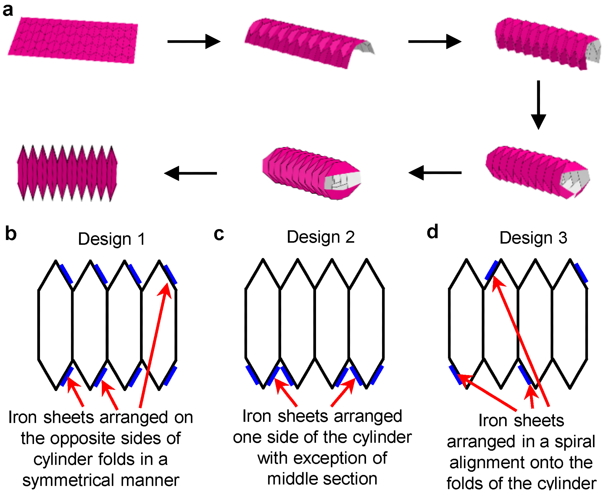
Figure 1. (a) Steps involved in the folding of the origami robot. (b) Design 1 arrangement of iron sheets in origami robot. (c) Design 2 arrangement of iron sheets in origami robot. (d) Design 3 arrangement of iron sheets in origami robot. Image Credit: Kalairaj, et al., 2021.
A design that permits compression and expansion in the horizontal direction without changing the vertical direction forms the basis of the soft robot, which mirrors the peristaltic movement in earthworms.
The folded structure of the soft robot was an octagonal cylinder whose open edges were closed with PVA adhesive. This forms the passive backbone of the soft robot.
The cylinder was coated with paramagnetic material and iron sheets were utilized as the paramagnetic material for assembly in the robot. Numerous iron sheets were arranged on the mountain folds of the paper backbone in three various configurations (design 1, design 2, and design 3), enabling different movements of the robot when actuated using a permanent magnet.
A neodymium-iron-boron (NdFeB) alloy cube permanent magnet was used to actuate the soft robot, which was kept on a thin flat surface. The permanent magnet (actuating or driving magnet) was moved in various paths to attain different robotic motions.
Results
Actuation of the robot was carried out at three various pathways of the permanent magnet. The equivalent locomotion (rolling, peristaltic, and turning) were matched for the configurations (design 1, design 2, and design 3) of the robot in the explored environments (board, sandpaper, and sand).
The estimated relative friction co-efficient of the three environments showed that the corrugated board had the lowest co-efficient while sand had the greatest coefficient. Sandpaper exhibited having the intermediate value.
A specific motion of the actuation magnet induces a peristaltic motion with continuous contraction and expansion; the mechanism is displayed in Figure 2.
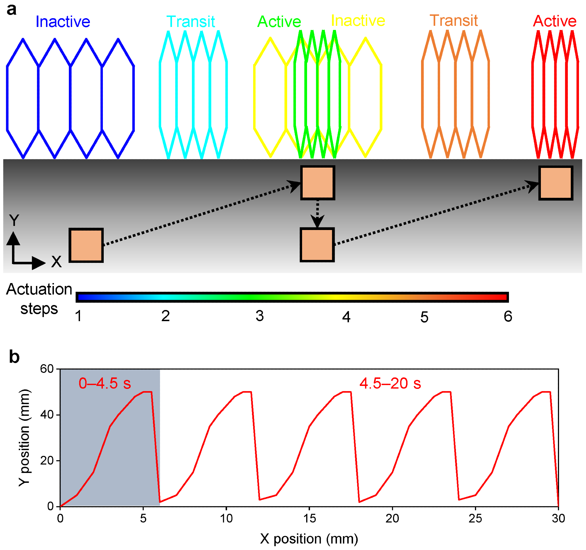
Figure 2. (a) Schematic showing the actuation mechanism of peristaltic motion of the soft robot actuated by a permanent magnet. (b) Pathway of the actuating magnet to generate the peristaltic motion of the robot. Image Credit: Kalairaj, et al., 2021.
Design 3, among the other configurations, displayed the best peristaltic motion.
Figure 3(a–c) shows the sequential pictures of the actuation of design 3 on board, sandpaper, and sand. In all environments, design 2 had negligible displacement along the X-direction (see Figure 3d,f,h) while design 1 showed minor displacement along the X-direction in both sandpaper and sand (Figure 3f,g).
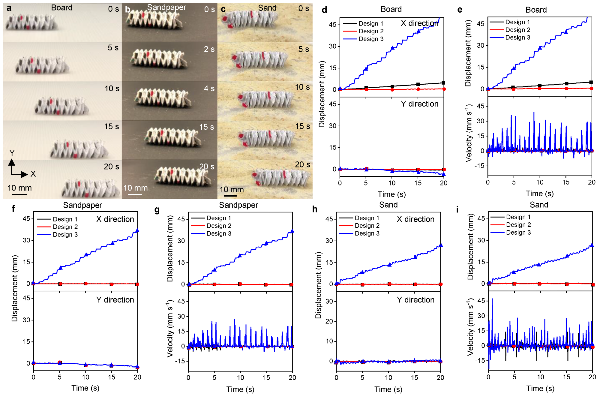
Figure 3. Performance of the peristaltic motion. (a) Time-lapse images of the peristaltic motion of the Design 3 origami robot inboard. (b) Time-lapse images of the peristaltic motion of the Design 3 origami robot in sandpaper. (c) Time-lapse images of the peristaltic motion of the Design 3 origami robot in the sand. (d) Time-resolved displacement in X and Y directions of the origami robot on board. (e) Time-resolved displacement and velocity of the origami robot on board. (f) Time-resolved displacement in X and Y directions of the origami robot in sandpaper. (g) Time-resolved displacement and velocity of the origami robot in sandpaper. (h) Time-resolved displacement in X and Y directions of the origami robot in the sand. (i) Time-resolved displacement and velocity of the origami robot in the sand. Image Credit: Kalairaj, et al., 2021.
Figure 3e depicts the velocity and displacement of the three configurations at the time of peristaltic motion on board, sandpaper, and sand. The researchers analyzed the actuation of individual segments to observe the actuation mechanism (See Figure 4).
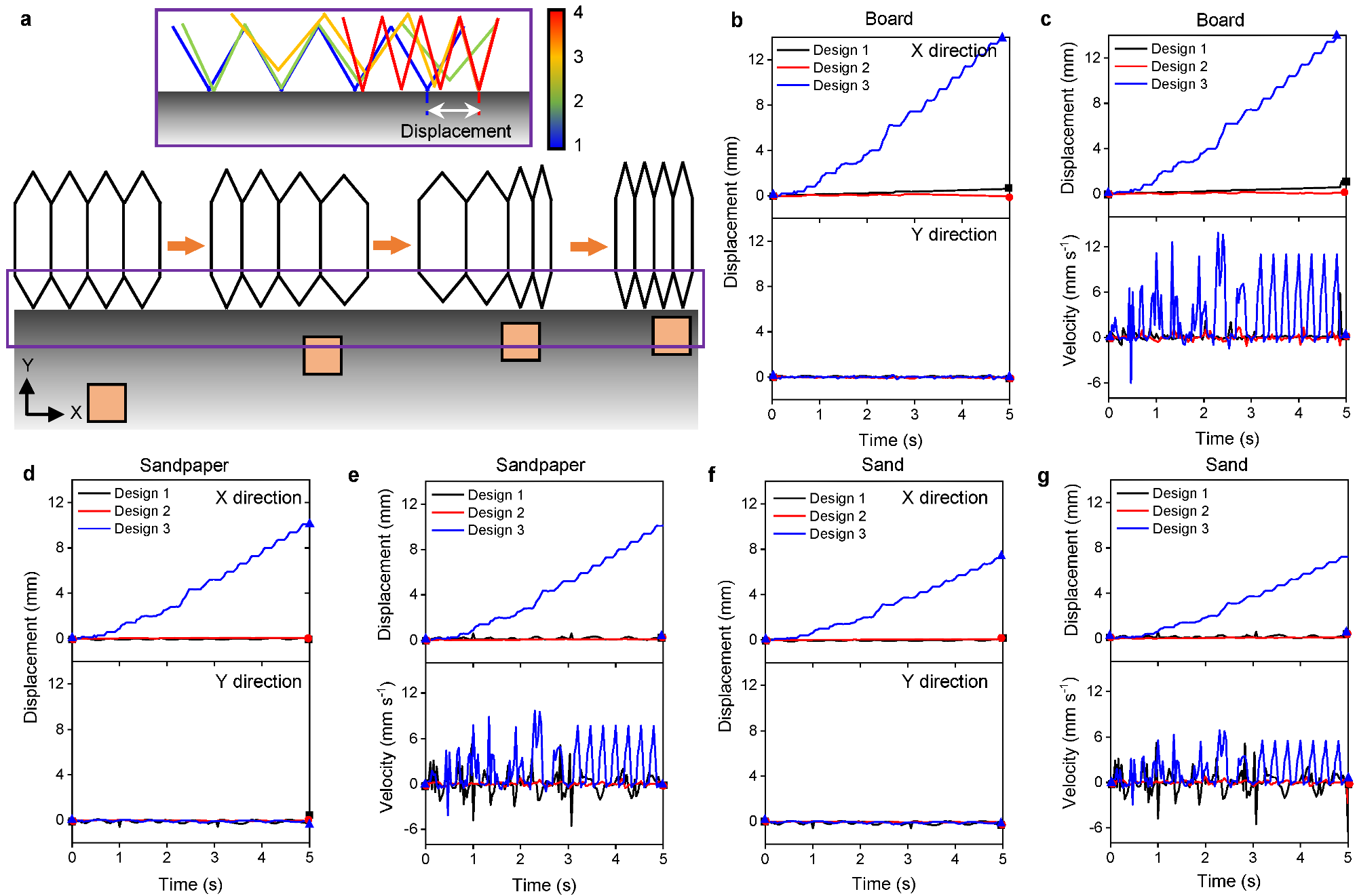
Figure 4. Performance of the individual segment during peristaltic motion. (a) Time-lapse images of the peristaltic motion of the Design 3 origami robot on board. (b) Time-lapse images of the peristaltic motion of the Design 3 origami robot in sandpaper. (c) Time-lapse images of the peristaltic motion of the Design 3 origami robot in the sand. (d) Time-resolved displacement in X and Y directions of the origami robot on board. (e) Time-resolved displacement and velocity of the origami robot on board. (f) Time-resolved displacement in X and Y directions of the origami robot in sandpaper. (g) Time-resolved displacement and velocity of the origami robot in sandpaper. (h) Time-resolved displacement in X and Y directions of the origami robot in the sand. (i) Time-resolved displacement and velocity of the origami robot in the sand. Image Credit: Kalairaj, et al., 2021.
The soft robot rolls along its length by a specific motion of the actuation magnet (see Figure 5a). By dragging it along the X-direction, the rotating and rolling mechanism of the robot can be achieved.
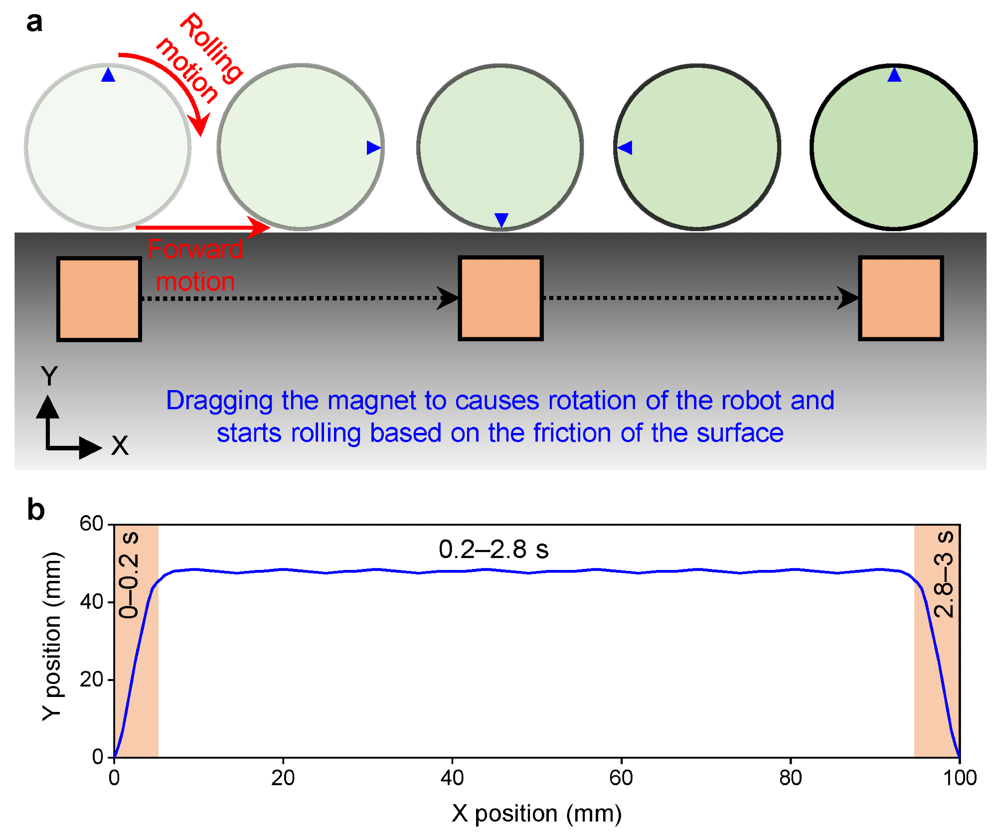
Figure 5. (a) Schematic showing the actuation mechanism of the rolling motion of the robot. (b) Pathway of the actuating magnet to generate the rolling motion of the robot. Image Credit: Kalairaj, et al., 2021.
Results indicated that design 3 showcased the best rolling performance on board, sandpaper, and sand (see Figure 6a–c), while the largest displacement and velocity of design 3 is on board.
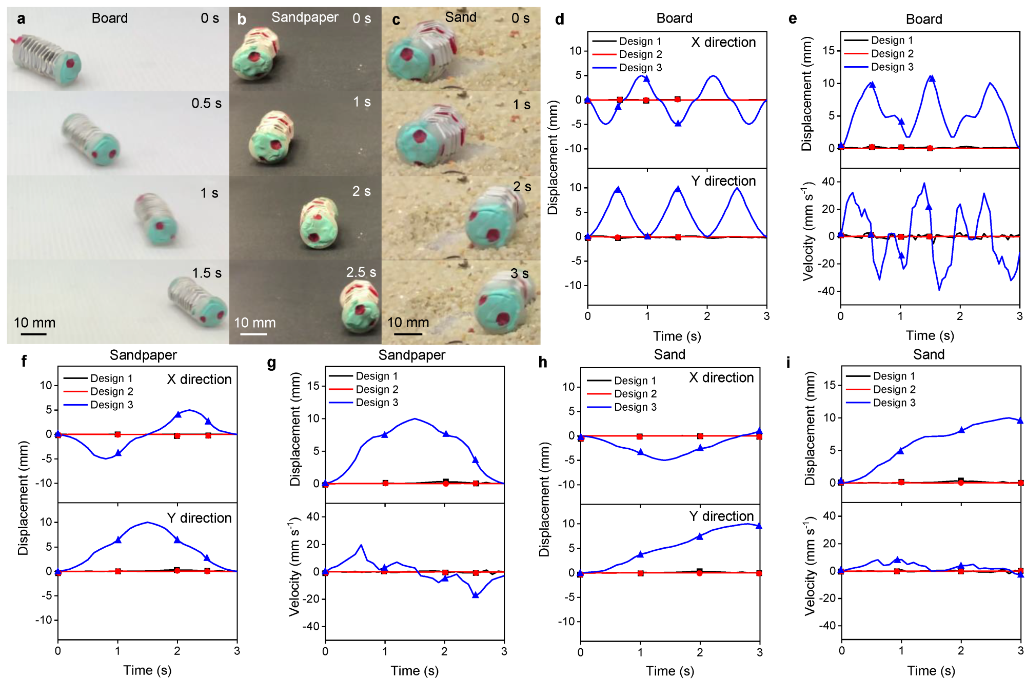
Figure 6. Performance of the rolling motion. (a) Time-lapse images of rolling motion of the Design 3 origami robot on board. (b) Time-lapse images of rolling motion of the Design 3 origami robot in sandpaper. (c) Time-lapse images of rolling motion of the Design 3 origami robot in the sand. (d) Time-resolved displacement in X and Y directions of the origami robot on board. (e) Time-resolved displacement and velocity of the origami robot on board. (f) Time-resolved displacement in X and Y directions of the origami robot in sandpaper. (g) Time-resolved displacement and velocity of the origami robot in sandpaper. (h) Time-resolved displacement in X and Y directions of the origami robot in the sand. (i) Time-resolved displacement and velocity of the origami robot in the sand. Image Credit: Kalairaj, et al., 2021.
Figure 6e, g, i shows the complete displacement and the velocities during the rolling motion.
When actuated in a specific motion, the magnet makes the robot bend or turn. The robot's initial and final position and its overall displacement measurement of the path traced by the actuating magnet during actuation are depicted in Figure 7.
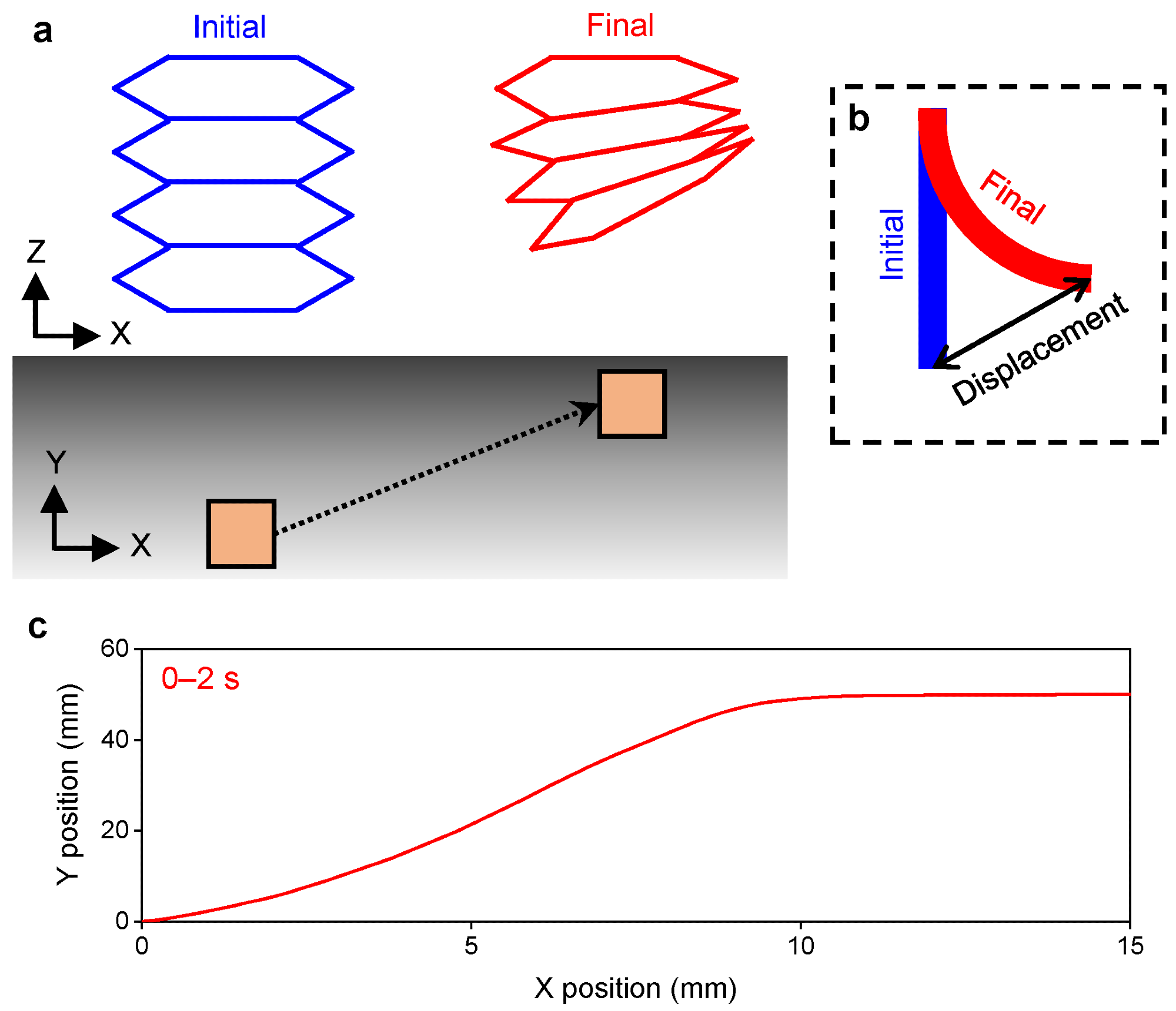
Figure 7. (a) Schematic showing the actuation mechanism of turning motion of the soft robot actuated by a permanent magnet. (b) Schematic showing the displacement in the body of the robot during turning motion. (c) Pathway of the actuating magnet to generate the turning motion of the robot. Image Credit: Kalairaj, et al., 2021.
Design 1 of the three configurations demonstrates the best turning performance in all environments, along with the highest displacement and velocity on board (see Figure 8).
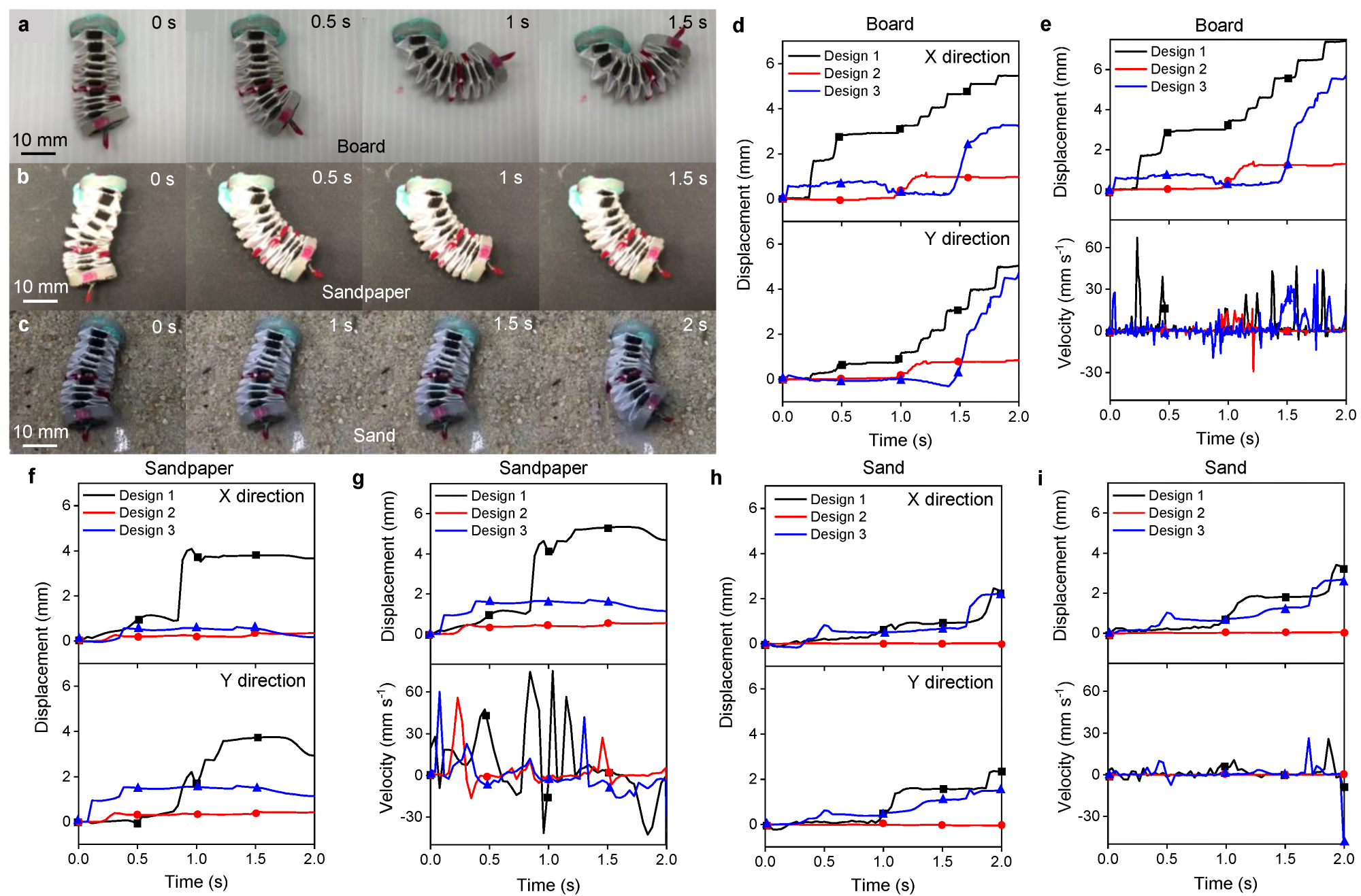
Figure 8. Performance of the turning motion. (a) Time-lapse images of turning motion of the Design 1 origami robot on board. (b) Time-lapse images of turning motion of the Design 1 origami robot in sandpaper. (c) Time-lapse images of turning motion of the Design 1 origami robot in the sand. (d) Time-resolved displacement in X- and Y-directions of the origami robot on board. (e) Time-resolved displacement and velocity of the origami robot on board. (f) Time-resolved displacement in X- and Y-directions of the origami robot in sandpaper. (g) Time-resolved displacement and velocity of the origami robot in sandpaper. (h) Time-resolved displacement in X- and Y-directions of the origami robot in the sand. (i) Time-resolved displacement and velocity of the origami robot in the sand. Image Credit: Kalairaj, et al., 2021.
Applications
Bringing about changes in the robot can enable its use in various fields, particularly the biomedical sector.
Substituting the paper backbone with other materials like PET (polyethylene terephthalate) or PEEK (polyether ether ketone) enables usage in fluidic environments; biocompatible materials like hydrogels can also be incorporated for use.
A small camera can be attached to the robot, enabling its use as an endoscope.
Conclusion
The study demonstrated a magnetically actuated origami folded cylinder that carries out various locomotions (peristaltic, rolling, and turning). The displacement and velocity profiles were compared in various sandpaper, board, and sand environments.
The performance of the soft robot analyzed reveals that design 1 is best suited for turning motion and that design 3 is best for peristaltic and rolling movements. The soft nature and the size of the robot restrict it from damaging the tissues, thus allowing use in biomedical applications.
However, the speed of the developed robot requires further modification, which can be addressed by replacing the iron sheets.
Minimizing the size of the soft robot may also increase its potential future applications.
Continue reading: Assembling the Foundations of Soft Robot Systems with Worm Blobs.
Journal Reference:
Kalairaj, M. S., Cai, C. J., Pavitra, S., Ren, H. (2021) Untethered Origami Worm Robot with Diverse Multi-Leg Attachments and Responsive Motions under Magnetic Actuation. Robotics, 10(4), p. 118. Available at: https://www.mdpi.com/2218-6581/10/4/118/htm
References and Further Reading
- Banerjee, H., et al. (2018) Single-motor controlled tendon-driven peristaltic soft origami robot. Journal of Mechanisms and Robotics, 10, p. 064501. doi.org/10.1115/1.4041200.
- Yang, H., et al. (2019) Graphene Oxide-Enabled Synthesis of Metal Oxide Origamis for Soft Robotics. ACS Nano, 13, pp. 5410–5420.
- Yang, H., et al. (2019) Multifunctional metallic backbones for origami robotics with strain sensing and wireless communication capabilities. Science Robotics, 4, p. 59. doi.org/10.1126/scirobotics.aax7020.
- Paez, L., et al. (2016) Design and analysis of a soft pneumatic actuator with origami shell reinforcement. Soft Robotics, 3, pp. 109–119.
- Zhai, Z., et al. (2018) Origami-inspired, on-demand deployable and collapsible mechanical metamaterials with tunable stiffness. Proceedings of the National Academy of Sciences USA, 115, pp. 2032–2037. doi.org/10.1073/pnas.1720171115.
- Reid, A., et al. (2017) Geometry and design of origami bellows with tunable response. Physical Review E, 95, p. 013002. doi.org/10.1103/PhysRevE.95.013002.
- Wang, F., et al. (2016) Folding to curved surfaces: A generalized design method and mechanics of origami-based cylindrical structures. Scientific Reports, 6, p. 33312. doi.org/10.1038/srep33312.
- Schenk, M., et al. (2014) Review of inflatable booms for deployable space structures: Packing and rigidization. Journal of Spacecraft Rockets, 51, pp. 762–778. doi.org/10.2514/1.A32598.
- Cowan, B & Von Lockette, P R (2017) Fabrication, characterization, and heuristic trade space exploration of magnetically actuated Miura-Ori origami structures. Smart Materials and Structures, 26, p. 045015. doi.org/10.1088/1361-665X/aa5a9e.
- Kuribayashi, K., et al. (2006) Self-deployable origami stent grafts as a biomedical application of Ni-rich TiNi shape memory alloy foil. Materials Science and Engineering A, 419, pp. 131–137. doi.org/10.1016/j.msea.2005.12.016.
- Camarillo, D. B., et al. (2008) Mechanics modeling of tendon-driven continuum manipulators. IEEE Transactions on Robotics, 24, pp. 1262–1273. doi.org/10.1109/TRO.2008.2002311.
- Dong, S. (2012) Review on piezoelectric, ultrasonic, and magnetoelectric actuators. Journal of Advanced Dielectrics, 2, p. 1230001. doi.org/10.1142/S2010135X12300010.
- Conway, N. J., et al. (2007) A strain amplifying piezoelectric MEMS actuator. Journal of Micromechanics and Microengineering, 17, p. 781. doi.org/10.1088/0960-1317/17/4/015.
- Bowen, L., et al. (2016) Trade space exploration of magnetically actuated origami mechanisms. Journal of Mechanics and Robotics, 8, p. 031012. doi.org/10.1115/1.4032406.
- Onal, C. D., et al. (2012) An origami-inspired approach to worm robots. IEEE/ASME Transactions on Mechatronics, 18, pp. 430–438. doi.org/10.1109/TMECH.2012.2210239.
- Kalairaj, M. S., et al. (2019) Hydrogel-matrix encapsulated Nitinol actuation with self-cooling mechanism. RSC Advances, 9, pp. 34244–34255. doi.org/10.1039/C9RA05360C.
- Kalairaj, M. S., et al. (2020) Nitinol actuated soft structures towards transnasal drug delivery: A pilot cadaver study. Medical & Biological Engineering & Computing, 58, pp. 611–623. doi.org/10.1007/s11517-019-02102-x.
- Kalairaj, M. S., et al. (2020) Needle-size bending actuators based on controlled nitinol curvatures and elastic structures. Journal of Mechanisms and Robotics, 12, p. 031015. doi.org/10.1115/1.4045646.
- Banerjee, H., et al. (2021) Highly Stretchable Flame-Retardant Skin for Soft Robotics with Hydrogel–Montmorillonite-Based Translucent Matrix. Soft Robotics. doi.org/10.1089/soro.2020.0003.
- Zhang, S., et al. (2021) Programmable and reprocessable multifunctional elastomeric sheets for soft origami robots. Science Robotics, 6, p. eabd6107. doi.org/10.1126/scirobotics.abd6107.
- Tang, D., et al. (2021) Origami-inspired magnetic-driven soft actuators with programmable designs and multiple applications. Nano Energy, 89, p. 106424. doi.org/10.1016/j.nanoen.2021.106424.
- Salerno, M., et al. (2017) A low profile electromagnetic actuator design and model for an origami parallel platform. Journal of Mechanisms and Robotics, 9, p. 041005. doi.org/10.1115/1.4036425.
- Cai, C. J., et al. (2020) Diversified and untethered motion generation via crease patterning from magnetically actuated caterpillar-inspired origami robot. IEEE/ASME Transactions on Mechatronics, 26, pp. 1678–1688. doi.org/10.1109/TMECH.2020.3028746.
- Xiang, X., et al. (2017) Large deformation of an arc-Miura structure under quasi-static load. Composite Structures, 182, pp. 209–222. doi.org/10.1016/j.compstruct.2017.09.023.
- Fang, H., et al. (2017) Origami-based earthworm-like locomotion robots. Bioinspiration & Biomimetics, 12, p. 065003. doi.org/10.1088/1748-3190/aa8448.
- Zhang, Q., et al. (2021) Yoshimura-origami Based Earthworm-like Robot With 3-dimensional Locomotion Capability. Frontiers in Robotics & AI, 8, p. 271. doi.org/10.3389/frobt.2021.738214.